- Noise Reducing Antenna for MW and LW, Noise reducing Antenna or Interference Reducing Antennas by Denzil Wraight.
- Wire Antenna , Wire Antenna for 6 Meter SSB/CW.
Long wave band, medium wave band, short wave band commonly used long wire as antennas . A long wire antenna is one that is long compared to a wavelength . A minimum length is one-half wave- length. However, antennas that are at least several wavelengths long are needed to obtain good gain and directional characteristics. Constructing long wire antennas is simple, and there are no critical dimensions or adjustments. A long wire antenna will accept power
and radiate it well on any frequency for which its overall length is not less than one-half wavelength.
 |
| Long wave Antenna construction design |
The gain and take-off angle of a long wire antenna depend on the antenna's length. The longer the antenna, the more gain, and the lower the take-off angle. Gain has a simple relationship to length; however, take-off angle is a bit more complicated. A long wire antenna radiates a cone of energy around the tie wire, much like a funnel with the antenna wire passing through the funnel opening. The narrow part of the funnel would be the feed point, and the open part would be toward the distant station. If the funnel were cut in half, the resulting half cone would represent the pattern of the antenna. As the antenna is lengthened, the cone of radiation (funnel) moves closer and closer to the wire.
 |
| Long wave antenna radiation pattern |
changes as the wire is lengthened. The patterns represent a view from directly below the antenna.
In the three-wavelength pattern, for very low-angle radiation, posi- tion the wire somewhat away from the direction of the distant sta- tion so that the main lobe
of radiation points at the receiving station. If a higher take-off angle is required, point the wire directly at the distant station.
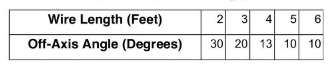 |
| LW Antenna Off Axis Angle Table |
For take-off angles from 5 to 25 feet, the following general off-axis angles will provide satisfactory radiation on toward the distant station To make a long wire antenna directional, place a terminating device at the distant station end of the antenna. The terminating device should be a 600-ohm, noninductive resistor capable of absorbing at least one-half of the transmitter power. Terminating resistors are components of some radio sets but can also be fabricated locally using supply system components (100-watt, 106-ohm resistor).
Constructing a long wire antenna requires only wire, support poles, insulators, and a terminating resistor (if directionality is desired). The only requirement is that the antenna be strung in as straight a line as the situation permits. The antenna is only 15 to 20 feet above ground, so tall support structures are not required.
The antenna is normally fed through a coupler that can match the antenna's 600- ohm impedance. Coaxial cable can be used if a 12 to 1 balun is available to convert the coaxial cable 50-ohm impedance to the required 600 ohms. Vertical radiation plots of this antenna are not presented because of the great variation in the pattern as the length changes. For take-off angles between 5 and 25 feet, use the off-axis graph as shows in table and the gain versus length graph to determine the proper antenna length.
 |
| LW Antenna Gain versus Length |
Characteristics LW Antenna are—
Frequency range: 2 to 30 MHz
Polarization: Vertical
Power capability: 1 ,000 watts
Radiation pattern Azimuthal (bearing): Bidirectional with terminating resistor
Vertical (take-off angle): Depends on length
No comments:
Post a Comment