Antenna Handbook : Complete free tutorial antennas design , Electronics Components and Circuits, Telecommunications, Cellular Networks, Satellite, broadband internet Networks, diy antenna , booster antenna filter antenna , software antenna , implementation and software programming , electronics ebook free download !
Crystal Tester Circuit
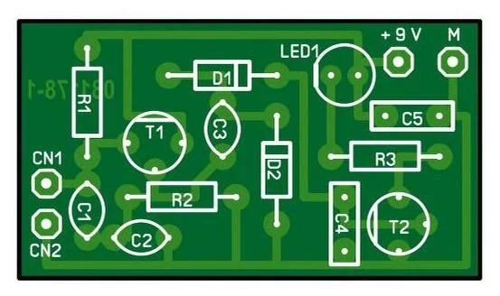
The circuit is use for test Quartz Crystal from 1 MHz to 50 MHz, if the crystal X1 good enough, sinewave will appears on Emiter T1 BF494 , and rectified by D2 IN4148 , drive D1 IN4148 and will charge Capacitor C4 until enough voltage to turn on Transistor BC547 and make the LED 1 on. This circuit using 9 V battery for enough consumption , below is PCB you can design . ( Source : Elektor Summer circuit)
Wideband Spark Transmissions Signal Receiver
This is circuit for Fun, receive spark transmissions signal from switch on off light , motors, high voltage lightning , electric motors can detected by this receiver on short wave band.
AM SW Converter with NE602
If you have old AM radio , you can use this circuit to change to Short Wave Radio, and tune the Short Wave frequency and start listening Short Wave around the world. The AM SW short wave radio can works from 1.6 MHz until 10 MHz by C1 with various values. from 150 pF until 10 pF , or you can use Trimmer Capacitor from 0-200 pF. For Crystals X1 can use 34.545 MHZ overtone crystal.
As datasheet NE602 describe , the features of this IC :
* Low current consumption : typical 2.4 mA
* Excellent noise figure : < 4.7 dB typical at 45 MHz
* High Operating frequency
* Excellent gain : intercept and sensitivity
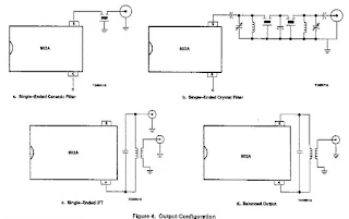
* Low external parts count ; suitable for crystal / ceramics filter
NE602 Pin Out :
Test Configuration for NE602 , look at Crystal on Pin 6.
Applications :
* Portable Radio
* Cellular Radio
Example for Cellular Radio Application :
* VHF Transceivers
* RF Data Links
* HF / VHF Frequency conversion
* Instrumentation frequency conversion
* Broadband LANs
Voice Memory Circuit Using Single Chip ISD1416 from Winbond
Voice IC recording system memory , ISD1416 from Winbond can use for many application such Answering Machine Phone, Talking Clocks also for private application such as in Public Services to tell People How To use Toilet, private toilet by record instruction for 2 minutes.
The Features of ISD1416 :
* Easy to use single chip voice record/playback solution
* High quality, natural voice/audio reproduction
* Push button interface
- Playback can be edge or level activated
* Single chip durations of 16 and 20 seconds
* Automatic power down mode
- Enters standby mode immediately following a record or playback cycle
- Standby current 0.5 uA (typical)
* Zero power message storage
- Eliminates battery backup circuits
* Fully addressable to handle multiple messages
* 100 year message retention (typical)
* 100,000 record cycles (typical)
* On-chip clock source
* No programmer or development system needed
* Single +5 volt power supply
* Available in die form, DIP, and SOIC packaging
* Industriall temperature (-40 Celcius degree to +85 Celcius degree) versions available
ISD 1400 Series Pinouts
Application Note example from datasheet ISD1416
For datasheet ISD1416 Please click here.
Simple Remote Control Tester
When your remote control TV problems , because not works well , you can use this circuit to check .
This circuit using BP103 which is photo transistor who will response to infra red spectrum when remote control TV problem.
Transistor BC548 will biases and turn LED D1 will flash when you test your remote by pressing the button and make sure the infra red of remote works well. Check it Out!
This circuit using BP103 which is photo transistor who will response to infra red spectrum when remote control TV problem.
Transistor BC548 will biases and turn LED D1 will flash when you test your remote by pressing the button and make sure the infra red of remote works well. Check it Out!
We have Generic Universal Tv Ir Remote Control Decoder Tester Infrared Remote Control Testing. with this tool you can answer the questions :
(1)How to confirm different TV remote controls can be compatible with each other?
(2)My TV remote control doesn't work, if you don't have the one I need,which model can take place of it?
Use this to test functionality of the remotes before listing them. Super easy to use and does exactly what it is supposed to..
Free Electricity Using Magnet and AC Motor
Magnet Neodymium circle , Big Magnet (blue) replace on between small magnet ( orange circle magnet). Small magnet replace with strong glue on Axis of AC Motor , uses 3 small magnet. And Big magnet glue on static body of AC Motor . Ignition Piezo connected to pole of motor . And after everything is done connected , tested by push the Piezo Ignition on , just once , and the AC Motor will running , and magnet will generate current and supply to bulb, and the bulb light on .
Subscribe to:
Posts (Atom)


