UNITED STATES PATENT OFFICE.
NIKOLA TESLA, OF NEW YORK, N. Y.
APPARATUS FOR THE UTILIZATION OF RADIANT ENERGY.
SPECIFICATION forming part of Letters Patent No. 685,957, dated November 5, 1901.
Application filed March.21, 1901, Serial No. 52,153, (No model.)
To all whom it my concern:
Beit known that I, NIKOLA TESLA, a citizen of the United States, residing at the borough of Manhattan, in the city, county, and State
of New York, have invented certain new and useful Improvements in Apparatus for the
Utilization of Radiant Energy, of which the following is a specification, reference being had to the drawings accompanying and forming a part of the same.
It is well known that certain radiations
such as those of ultra-violet light, cathodic, Roentgen rays, or the like-possess the property of charging and discharging conductors of electricity, the discharge being particu larly noticeable when the conductor upon Which the rays impinge is negatively electri
fied.
These radiations are generally con sidered to be ether vibrations of extremely small Wave lengths, and in explanation of the
phenomena noted it has been assumed by
some authorities that they ionize or render conducting the atmosphere through which they are propagated.
My own experiments and observations, however, lead me to con
clusions more in accord with the theory here
tofore advanced by me that sources of such radiant energy throw off with great velocity minute particles of matter which are strongly electrified, and therefore capable of charging
an electrical conductor, or, even if not so, may at any rate discharge an electrified con
ductor either by carrying off bodily its charge
or otherwise.
My present application is based upon a dis
covery which I have made that when rays or radiations of the above kind are permitted to
fall upon an insulated conducting-body con
nected to one of the terminals of a condenser
while the other terminal of the same is made by independent means to receive or to carry
away electricity a current flows into the con
denser so long as the insulated body is exposed to the rays, and under the conditions
hereinafter specified an indefinite accumu
lation of electrical energy in the condenser takes place.
This energy after a suitable
time interval, during which the rays are al
lowed to act, may manifest itself in a pow erful discharge, which may be utilized for the operation or control of mechanical or elec
trical devices or rendered useful in many other ways.
In applying my discovery I provide a condenser, preferably of considerable electro
static capacity, and connect one of its termi
nals to an insulated metal plate or other con ducting-body exposed to the rays or streams
It is very important, par ticularly in view of the fact that electrical
energy is generally supplied at a very slow
rate to the condenser, to construct the same I use, by preference, the best quality of mica, as dielectric, taking every possible precaution in insulating the
armatures, so that the instrument may with
stand great electrical pressures without leak
ing and may leave no perceptible electrifi cation when discharging instantaneously.
In
practice I have found that the best results
are obtained with condensers treated in the
manner described in a patent granted to me
February 23, 1897, No. 577,671.
Obviously the
above precautions should be the more rigor ously observed the slower the rate of charg ing and the smaller the time interval during which the energy is allowed to accumulate in
the condenser.
The insulated plate or con ducting-body should present as large a sur
face as practicable to the rays or streams of
matter, I having ascertained that the amount of energy conveyed to it per unit of time is
under otherwise identical conditions propor tionate to the area exposed, or nearly so.
Furthermore, the surface should be clean and preferably highly polished or amalgamated. The second terminal or armature of the con
denser may be connected to one of the poles of a battery or other source of electricity or
to any conducting body or object whatever of
such properties or so conditioned that by its
means electricity of the required sign will be
supplied to the terminal.
A simple way of supplying positive or negative electricity to
the terminal is to connect the same either to
an insulated conductor supported at Some height in the atmosphere or to a grounded con
ductor, the former, as is well known, furnish ing positive and the latter negative electric ity. As the rays or supposed streatms of matter generally convey a positive charge to the
first condenser-terminal, which is connected
to the plate or conductor above mentioned, I
usually connect the second terminal of the
condenser to the ground, this being the most convenient way of obtaining negative elec
tricity, dispensing with the necessity of pro viding an artificial source.
In order to utilize for any useful purpose the energy accu
mulated in the condenser, I furthermore connect to the terminals of the same a circuit in
cluding an instrument or apparatus which it
is desired to operate and another instrument
or device for alternately closing and opening the circuit.
This latter may be any form of
circuit-controller, with fixed or movable parts
or electrodes, which may be actuated either
by the stored energy or by independent means.
My discovery will be more fully understood
from the following description and annexed
drawings, to which reference is now made, and in which
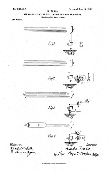
Figure 1 is a diagram showing the general arrangement of apparatus as usually em
ployed. Fig. 2 is a similar diagram illustrat
ing more in detail typical forms of the devices
or elements used in practice, and Figs. 3 and
4 are diagrammatical representations of modified arrangements suitable for special pur poses.
As illustrative of the manner in which the
several parts or elements of the apparatus in
one of its simplest forms are to be arranged and connected for useful operation, reference
is made to Fig. 1, in which C is the condenser, P the insulated plate or conducting - body which is exposed to the rays, and P' another plate or conductor which is grounded, all be
ing joined in series, as shown.
The terminals
TT of the condenser are also connected to a
circuit which includes a device R to be oper ated and a circuit-controlling device d of the
character above referred to.
The apparatus being arranged as shown, it
Will be found that when the radiations of the
Sun or of any other source capable of pro ducing the effects before described fall upon the plate Pan accumulation of electrical
energy in the condenser C will result.
This phenomenon, I believe, is best explained as
follows: The sun, as well as other sources of radiant energy, throws off minute particles of
matter positively electrified, which, impinging
upon the plate P, communicate continuously
an electrical charge to the same.
The opposite terminal of the condenser being con
nected to the ground, which may be considered as a vast reservoir of negative electricity,
a feeble current flows continuously into the
condenser, and inasmuch as these supposed particles are of an inconceivably small radius
or curvature, and consequently charged to a relatively very high potential, this charging of
the condenser may continue, as I have ac
tually observed, almost indefinitely, even to
the point of rupturing the dielectric.
If the device d be of such character that it will op erate to close the circuit in which it is in
cluded when the potential in the condenser
has reached a certain magnitude, the accumu
lated charge will pass through the circuit, which also includes the receiver R, and oper ate the latter.
In illustration of a particular form of ap paratus which may be used in carrying out
my discovery I now refer to Fig. 2. In this
figure, which in the general arrangement of
the elements is identical to Fig. 1, the device
d is shown as composed of two verythin con ducting-plates it, placed in close proximity and very mobile, either by reason of extreme
flexibility or owing to the character of their
support.
To improve their action, they should
be inclosed in a receptacle, from which the
I air may be exhausted. The plates t t are
connected in series with a working circuit, including a suitable receiver, which in this
case is shown as consisting of an electromag net M, a movable armature a, a retractile spring b, and a ratchet-wheel w, provided with a spring-pawl 1, which is pivoted to ar
mature a, as illustrated.
When the radia
tions of the sun or other radiant source fall
upon plate P, a current flows into the con
denser, as above explained, until the potential therein rises sufficiently to attract and bring into contact the two plates it, and
thereby close the circuit connected to the two
condenser-terminals.
This permits a flow of
current which energizes the magnet M, causing it to draw down the armature a, and im
part a partial rotation to the ratchet-wheel
(U. As the current ceases the armature is
retracted by the spring b, without, however, moving the wheel v.
With the stoppage of
the current the plates it cease to be attracted and separate, thus restoring the circuit to its original condition.
Fig. 3 shows a modified form of apparatus used in connection with an artificial source
of radiant energy, which in this instance may be an arc emitting copiously ultra-violet rays.
A suitable reflector may be provided for con centrating and directing the radiations. A
magnet R and circuit-controller d are ar ranged as in the previous figures; but in the
present case the former instead of performing itself the whole Work only serves the purpose of alternately opening and closing a local
circuit, containing a source of current B and
a receiving or translating device D. The
controller d, if desired, may consist of two fixed electrodes separated by a minute air
gap or weak dielectric film, which breaks
down more or less suddenly when a definite
difference of potential is reached at the ter
minals of the condenser and returns to its
original state upon the passage of the dis charge.
Still another modification is shown in Fig. 4, in which the source S of radiant energy is
a special form of Roentgen tube devised by me, having but one terminal k, generally of
aluminium, in the form of half a sphere, with
a plain polished surface on the front side, from which the streams are thrown off. It
may be excited by attaching it to one of the terminals of any generator of sufficiently high electromotive force; but whatever apparatus be used it is important that the tube be ex
hausted to a high degree, as otherwise it might prove entirely ineffective.
The working or
discharge circuit connected to the terminals
TT of the condenser includes in this case the primary p of a transformer and a circuit controller comprising a fixed terminal or
brush t and a movable terminal t in the shape of a wheel, with conducting and insulating segments, which may be rotated at an arbi
trary speed by any suitable means. In in
ductive relation to the primary wire or coil p is a secondary S, usually of a much greater number of turns, to the ends of which is connected a receiver R. The terminals of the condenser being connected, as indicated, one
to an insulated plate P and the other to a grounded plate P", when the tube S is excited
rays or streams of matter are emitted from the same, which convey a positive charge to
the plate P and condenser-terminal T, while terminal T is continuously receiving nega tive electricity from the plate P'.
This, as
before explained, results in an accumulation of electrical energy in the condenser, which
goes on as long as the circuit including the primary p is interrupted. Whenever the cir
cuit is closed owing to the rotation of the terminal t, the stored energy is discharged through the primary p, this giving rise in the
secondary S to induced currents, which oper ate the receiver R.
It is clear from what has been stated above that if the terminal T is connected to a plate supplying positive instead of negative elec tricity the rays should convey negative elec
tricity to plate P.
The source S may be any form of Roentgen or Lenard tube; but it is obvious from the theory of action that in
55
Order to be very effective the electrical im pulses exciting it should be wholly or at least preponderatingly of one sign. If ordinary Symmetrical alternating currents are em
ployed, provision should be made for allow ing the rays to fall upon the plate P only during those periods when they are product ive of the desired result. Evidently if the radiations of the source be stopped or inter cepted or their intensity varied in any man
ner, as by periodically interrupting or rythmic ally varying the current exciting the source, there will be corresponding changes in the
action upon the receiver R, and thus signals may be transmitted and many other useful
effects produced.
Furthermore, it will be un
derstood that any form of circuit-closer which will respond to or be set in operation when a predetermined amount of energy is stored in
the condenser may be used in lieu of the device specifically described with reference to Fig. 2
and also that the special details of construction . and arrangement of the several parts of the
apparatus may be very greatly varied with
out departure from the invention.
Having described my invention, what I claim is
1. An apparatus for utilizing radiant en
ergy, comprising in combination a condenser,
one armature of which is subjected to the ac tion of rays or radiations, independent means for charging the other armature, a circuit and apparatus therein adapted to be operated or
controlled by the discharge of the condenser, as set forth.
2. An apparatus for utilizing radiant en
ergy, comprising in combination, a condenser,
one armature of which is subjected to the ac tion of rays or radiations, independent means
for charging the other armature, a local cir cuit connected with the condenser-terminals,
a circuit-controller therein and means adapted to be operated or controlled by the discharge of the condenser when the local circuit is closed, as set forth.
3. An apparatus for utilizing radiant en
ergy, comprising in combination, a condenser,
one terminal of which is subjected to the ac tion of rays or radiations, independent means
for charging the other armature, a local cir cuit connected with the condenser-terminals, a circuit-controller therein dependent for op eration on a given rise of potential in the con denser, and devices operated by the discharge of the condenser when the local circuit is closed, as set forth.
4. An apparatus for utilizing radiant en
ergy, comprising in combination, a condenser,
one terminal of which is subjected to the ac
tion of rays or radiations, and the other of which is connected with the ground, a circuit and apparatus therein adapted to be operated by the discharge of the accumulated energy in the condenser, as set forth.
5. An apparatus for utilizing radiant en
ergy, comprising in combination, a condenser,
one terminal of which is subjected to the ac
tion of rays or radiations and the other of which is connected with the ground, a local circuit connected with the condenser-termi
nals, a circuit-controller therein and means adapted to be operated by the discharge of
the condenser when the local circuit is closed, as set forth.
6. An apparatus for utilizing radiant en
ergy, comprising in combination, a condenser,
one terminal of which is subjected to the ac
tion of rays or radiations and the other of which is connected with the ground, a local
circuit connected with the condenser-termi
nals, a circuit-controller therein adapted to be operated by a given rise of potential in the
condenser, and devices operated by the dis charge of the condenser when the local circuit is closed, as set forth.
7. An apparatus for utilizing radiant energy, comprising a condenser, having one ter- adapted to be operated by a given rise of po minal connected to earth and the other to an tential in the condenser, as set forth.
elevated conducting-plate, which is adapted to receive the rays from a distant source of radiant energy, a local circuit connected with the condenser-terminals, a receiver therein, and a circuit - controller therefor which is adapted to be operated by a given rise of potential in the condenser, as set forth.
NIKOLA TESLA
Witnesses:
M.LAWSON DYER
RICHARD DONOVAN
Book About Nikola Tesla Lecture and Patents
Free Electricity Books
Here you can find books and e-books that useful for your further reference for knowing more about Free Electricity.

 The Installation :
 On his experiment,this device proved can reduce or saving the use of gasoline or diesel,and also reduce the CO Emission to the air. Last, I will post my experiment with this device on my diesel car to you.