The simple broadband TV antenna works at the 615- 765- MHz. Antenna has input impedance 300- Ohm at
the pass band. Antenna may be used with antenna
amplifier that has such input impedance.
The antenna is a variant of the famous Chireix- Mesny
Antenna.
Antenna may be used with coaxial cable with
broadband transformer. switched to the TV 150- MHz.
Figure 1 shows design of the antenna.
Figure 2
shows impedance of the antenna (antenna placed at
7- meter above the real ground). Figure 3 shows SWR
of the antenna (antenna placed at 7- meter above the
real ground). Figure 4 shows DD of the antenna
(antenna placed at 7- meter above the real ground).
The MMANA model of the Chireix- Mesny TV Antenna
may be loaded: http: //
www.antentop.org/018/chireix_018.htm
Note I.G.: Chireix- Mesny Antenna was designed in
France by Henri Chireix, Chief Engineer of the Societe
Francaise Radiotelectrique, and Rene Mesny,
Professor of Hydrography in the French Navy. Papers
on the antenna were published (in different variations)
in the 1926- 1928s. Patent H. Chireix: French Patent #
216,757, filed Mar. 10, 1926.
Antenna originally was used for directive radiation and
reception at short waves. Lately the antenna was
widely used at VHF- UHF waves.
(Source : Antentop)
Below it is
described one of those antennas- it is a Rhombic
Antenna. Rhombic Antenna is easy to make and at the
same time has perfect parameters.
Rhombic Antennas are easy to build and at the same
time has high gain and good diagram directivity.
However the antennas have some lack. Such antennas
required lots space for installations and need at least
for masts instead one that used to support traditional
directional antennas.

Figure 1 shows design of the Rhombic Antenna.
Rhombic Antenna is a rhomb that hang up horizontally
at the ground. Feeder is connected on to one sharp
angle of the rhomb. Terminated resistor is connected
on to far sharp angle of the rhomb. The resistor’s value
should be equal to the impedance of the rhomb at the
working frequencies of the antenna. As usual the value
is near 700- Ohm. Working frequencies of the antenna
may have pass band in hundreds megahertz. So using
such matched resistor allows create a super broadband
antenna that has impedance near 700- Ohm at the
frequencies window in several hundred megahertz.
High gain and high directivity of the rhomb antenna
could be explained by combining gain and diagram
directivity of the parts of the antenna. The antenna
consists of four wires with traveling wave.
Figure 2
shows the combination. Each wire has own gain and
diagram directivity.
The gain and diagram directivity depends on ratio the
length of the wire to the working wavelength. So, the
summary gain and diagram directivity depends on the
ratio the length of the wire to the working wavelength
and to the sharp angle of the rhomb.
Table 1 shows data for Rhombic Antenna with different
parameters. To keep such parameters antenna should
be placed above the ground at height not less the 2- 3
wavelength of the working band of the antenna.
Antenna may be fed by open ladder line with wave
impedance 300… 600- Ohm. At this case the antenna
could be matched at all working frequencies band.
Antenna may be fed through a coaxial cable when two
simple matching transformers are used.

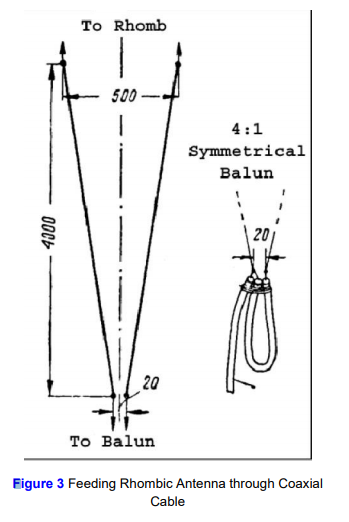
Figure 3
shows feeding Rhombic Antenna through a coaxial
cable. First transformer is a broadband transformer
made on two wire ladder line. It is two wires line with
varying wave impedance on the length.
The wave impedance of the line changes from 700- Ohm at rhomb side to 300- Ohm at coaxial cable
side.At coaxial cable side the coaxial cable should not
connect straight away to the line. Coaxial cable
connected to the line through a symmetrical
transformer 4:1 made on lengths of the used coaxial
cable. The transformer makes symmetrical and
provides matching of the Rhombic Antenna to coaxial
cable. Loop of the coaxial cable should have electrical
length lambda/2. To calculate such transformer you
need to know the shortening coefficient of the used coaxial cable.
It is possible to use coaxial cable with any wave
impedance- 50 or 75 Ohm. Matching impedance of the
4:1 transformer depends on the coaxial cable. At 50- Ohm cable it is got transformer 200:50- Ohm, at 75- Ohm cable it is got transformer 300:75- Ohm.
Transformer 300:75- Ohm should have best matching
result with open line transformer. There are lots link in
the internet how the transformer may be calculated.
One of them is:http://www.nlemma.com/calcs/dipole/balun.htm. When the coaxial
cable symmetrical transformer is used the broadband
of the antenna depends on the broadband of the
transformer. As usual coaxial cable transformer has
good matching at the 5% frequencies band calculated
from the central working frequency of the transformer.
So, when such transformer is used the broad band of
the Rhombic Antenna is limited to pass band of the
transformer.
Antenna may be made from a strand wire in diameter
2… 3- mm. It may be copper, aluminum or bimetal
(with copper or aluminum layer) wire. Terminated
resistor at the antenna may be any small power noninductive resistor. This one should be protected from
atmospheric influences. (Source : Antentop)
The simple broadband TV antenna works at the 580- 760- MHz. Passband of the antenna is 180- MHz.
Antenna has input impedance 300- Ohm at the pass
band.
The Design also can modified from Band frequency 470-806 and with impedance 50 Ohm.
Antenna may be used with antenna amplifier
that has such input impedance. Antenna may be used
with coaxial cable with broadband transformer.
The antenna is critical to any nearby metal subjects. Place the antenna with isolator connected to Antenna body and tower or antenna holder.
They can destroy the DD of the antenna. Space in 50
cm near the antenna should be free from such metal
or conductive subjects. If antenna is used for reception
purposes the best way is place low noise amplifier at
the antenna terminal.
LNA or Low Noise Amplifier can be made with 2SC3358 or 2SC3355, Low Noise Wideband Amplifier 0 - 1 GHz
 Figure 1 shows view of the antenna. Figure 2 shows
design of the antenna. Figure 3 shows impedance of
the antenna (antenna placed at 7- meter above the
real ground). Figure 4 shows SWR of the antenna
(antenna placed at 7- meter above the real ground).
Figure 5 shows DD of the antenna (antenna placed at
7- meter above the real ground).
The MMANA model of the Broadband TV Antenna
may be loaded: http: //
www.antentop.org/018/ur0gt_tv_018.htm (Source : Antentop with modification in content)
Figure 1 shows view of the antenna. Figure 2 shows
design of the antenna. Figure 3 shows impedance of
the antenna (antenna placed at 7- meter above the
real ground). Figure 4 shows SWR of the antenna
(antenna placed at 7- meter above the real ground).
Figure 5 shows DD of the antenna (antenna placed at
7- meter above the real ground).
The MMANA model of the Broadband TV Antenna
may be loaded: http: //
www.antentop.org/018/ur0gt_tv_018.htm (Source : Antentop with modification in content)


