For good reception of uhf tv and digital tv, bandpass filter is a choice for avoiding another signal beside uhf tv channel signal. there are 3 type of bandpass filter that be known , Butterworth, Chebyshev and Bessel filter design.
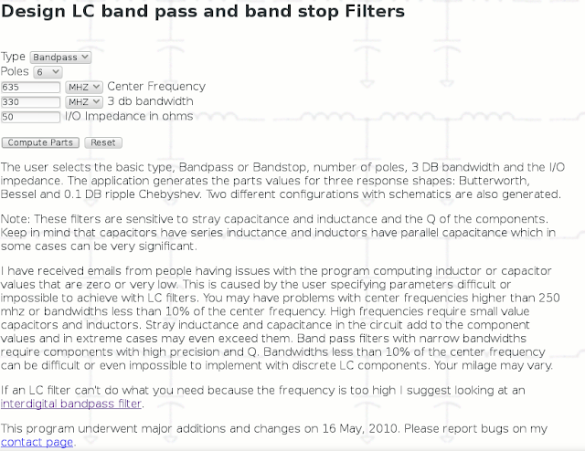
As shown in this design , I am using http://www.wa4dsy.net/filter/filterdesign.html software online design, or can also using Chebyshev design from http://www.changpuak.ch/electronics/chebyshev_bandpass.php
Input frequency center for 470-800 MHz, 635 MHz , select bandpass filter or bandstop filter design as menu shown.
after input frequency center, bandwidth of the filter 330 mhz, and the impedance input/output 50 ohms, than select compute parts and the result of filter design will be shown as below.
Antenna Handbook : Complete free tutorial antennas design , Electronics Components and Circuits, Telecommunications, Cellular Networks, Satellite, broadband internet Networks, diy antenna , booster antenna filter antenna , software antenna , implementation and software programming , electronics ebook free download !
Build This Digital TV Indoor Antenna 470-800 MHz
I get this idea after searching and studying literature from ARRL handbook, other sources and by experimenting several times. Although my design not perfectly design, but it shows several Channel TV in digital reception with good quality. And several of channels not in good quality. I think the future design of this antenna will give good performance for digital indoor TV antenna.
As mention in ARRL handbook, for high frequency , the equation for finding element length is :
L = 468 / Fo ( in Feet)
Where Fo = Center Frequency
If We design for 470 - 800 MHz , the center frequency will be Fo = 635 MHz, substitute to the equation :
L = 468 / 635 = 0.737 feet , convert to cm . 1 feet = 30.48 cm , so for 0.737 feet equals to :
L = 0.737 feet x 30.48 cm/feet = 22.46 cm , this is 1/2 lambda for UHF signal in 635 MHZ.
1/4 lambda will be 11.23 cm
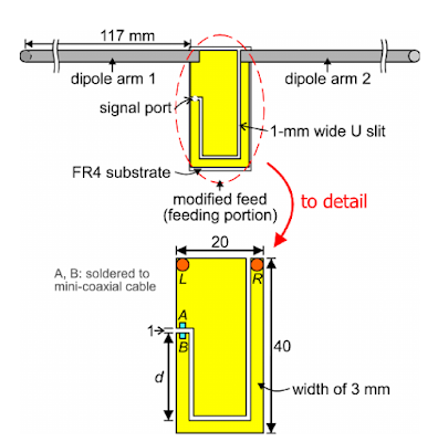
As I read in one of literature from S.W. Su and F.S. Chang from Lite On Technology Corporation , Taiwan and Department of Electronics Cheng Shiu University Taiwan. Wideband Rod Dipole Antenna with a modified feed for DTV Signal Reception.
From that literature we can have the design of PCB , feed gap, and dipole design.
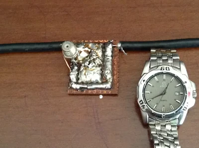
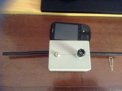
I use experiment PCB, and cut the corresponding to the design.The result of antenna as shown .
My design not exactly the same as the design from S.W. Su , i use 1/4 lambda for both arms.
9.3 dBi Yagi TV Antenna 470-800 MHz
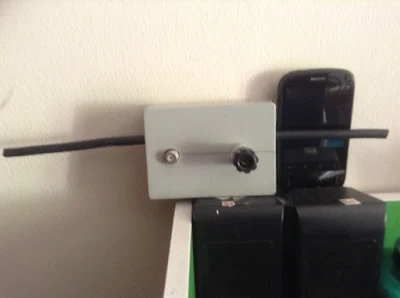
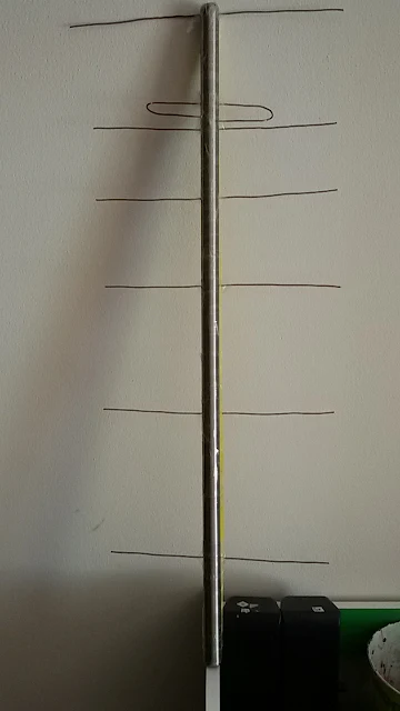
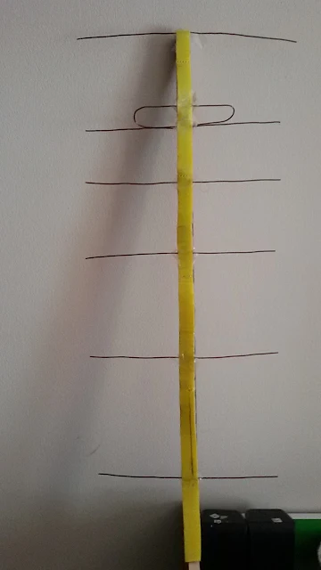
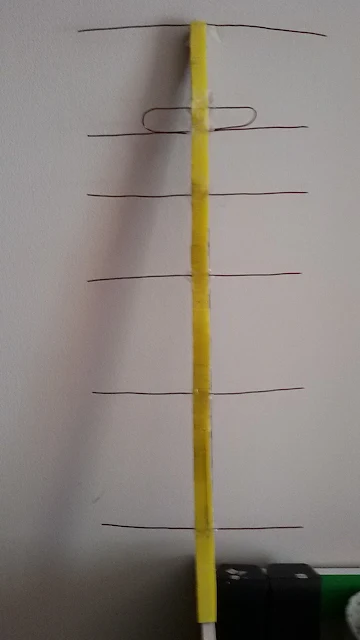
I build this Yagi antenna , using material that I have in home. I used boom from stainless steel , with boom length 583 mm. And using copper wire with diameter 1 mm as elements and reflector and driven element.
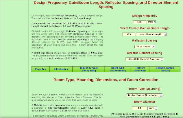
For wire length of elements and elements spacing. I used software for Yagi Antenna from K7MEM online Yagi Antenna calculator from Martin E. Meserve.
Thanks to Martin who has been simplest the process of calculating and designing in Yagi Antenna. Just enter the center frequency of Band frequency we want for antenna to cover, enter boom length or gain we want to get. Driven element diameter, parasitic element diameter and click the calculate in menu and get the result for Yagi antenna design in another page.
As my design in Yagi antenna, I design for Digital and Analog TV for frequency 470 MHz - 800 MHz Band.
I choose center frequency in 635 MHz.
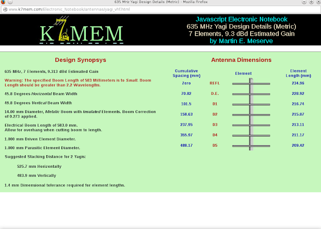
See the attachment result of my Yagi Antenna design.
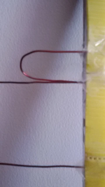
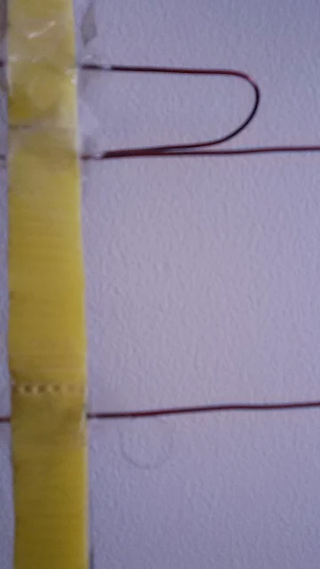
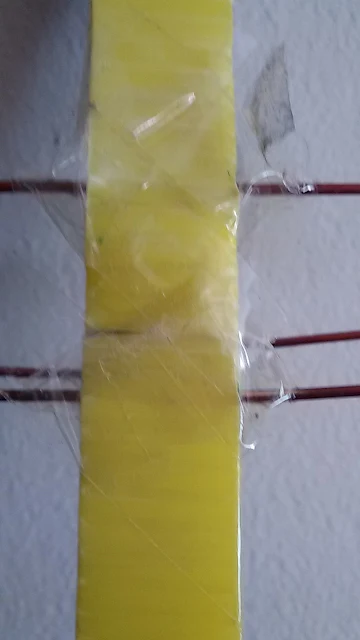
Because my design using Metal Boom Insulated , I used yellow plastic as insulated material and plug in the copper wire to this plastic and tight it with tape plastic.
As seen in picture , I am not yet connect the driven element to balun. The Balun design also calculated with K7MEM calculator in another page.
As seen in design picture, this antenna yagi have gain approximately 9.3 dBi.
My goals on this experiment to make sure that this design works in reality and can received TV signal more good than small antenna I have built later as Indoor antenna. I will publish later. I don't now how much gain this antenna have, but have good reception in several channel and also with no noise in several channel.
I will get back to connect this antenna to balun and connector and will see how the result in this week.
Sun Switch Using 2N3055 and BD139 Transistor


 2N3055 is Power Transistor and Amplifier Transistor for General Purpose and can act as Photo
Transistor by cutting the "hat cover" of this transistor. This photo transistor function of 2N3055 can be taking the advantage as switching function with transistor.
This circuit using 2 transistor which is 2N3055 and BD139. If there is no sun light or the light is not enough for Transistor 2N3005 to deliver, so R1 will give current to TR2 BD139 ,and this transistor will turn on Lamp on the Output of Circuit.
 If The Sun Light which flows to "hat cover" of TR1 2N3055 enough, TR1 will deliver and will grounded Base of TR2 BD139 and will Turn Off The Lamp.R2 and P1 will improve switching system of the Transistors and The Light of Lamp Intensity could be regulated by P1.
 If The Sun Light which flows to "hat cover" of TR1 2N3055 enough, TR1 will deliver and will grounded Base of TR2 BD139 and will Turn Off The Lamp.R2 and P1 will improve switching system of the Transistors and The Light of Lamp Intensity could be regulated by P1.
At the below figure is Stripboard or Veroboard for the circuit. This Veroboard using DIYLC software.
Parts Lists of Components :
Transistor TR1 2N3055
Transistor TR2 BD139
Resistor R1 4K7
Resistor R2 10K
Trimmer Resistor P1 1M
Lamp 9 V / 400 mA
Battery 12 V
Box for the Circuit
Transistor TR1 2N3055
Transistor TR2 BD139
Resistor R1 4K7
Resistor R2 10K
Trimmer Resistor P1 1M
Lamp 9 V / 400 mA
Battery 12 V
Box for the Circuit
Build This Simple Half Wave Dipole Antenna for Digital TV band 470-800 MHZ
The half-wavelength dipole is a balanced antenna consisting of two radiators that are each a quarter-wavelength, making a total of a half-wavelength. The antenna is usually installed horizontally with respect to the earth’s surface, so it produces a horizontally polarized signal.
In its most common configuration , the dipole is supported at each end by rope and end insulators. The rope supports are tied to trees, buildings, masts, or some combination of such structures. Ads Link
The length of the antenna is a half-wavelength. Keep in mind that the physical length of the antenna, and the theoretical electrical length, are often different by about 5 percent. A free-space half-wavelength is found from :
In a perfect antenna, that is self-supported many wavelengths away from any object,The Equation will yield the physical length. But in real antennas, the length calculated above is too long. The average physical length is shortened by up to about 5 percent because of the velocity factor of the wire and capacitive effects of the end insulators. A more nearly correct approximation (remember that word, it's important) of a half-wavelength antenna is
where :
L is the length of a half-wavelength radiator, in feet
FMHz is the operating frequency, in megahertz
For example : Calculate the approximate physical length for a half-wavelength dipole
operating on a frequency of 7.25 MHz.
Solution:
L=( 468/F(MHz) ) ft
= 468/7.25 ft = 64.55 ft
or, restated another way:
L = 64 ft 6.6 in
It is unfortunate that a lot of people accept Equation above as a universal truth, a kind of immutable law of The Universe. Perhaps abetted by books and articles on antennas that fail to reveal the full story, too many people install dipoles without regard for reality.
We will design Dipole antenna for Digital TV reception , as We know in literature the band frequency for TV reception between 470 MHz - 800 MHz. for this band frequency, we can calculate the centre frequency. The centre frequency for this band is 635 MHz.
The design of antenna , for balance the power reception of this antenna, by calculating design in centre frequency .
As the formula :
L = 468 /F
So,
L = 468/635 feet
L = 0.737 feet , this is 1/2 Lambda for centre frequency band of Digital TV reception.
For Dipole antenna design , between 2 arms of dipole antenna should be 1/2 lambda, so one arm of dipole antenna will be 1/4 Lambda .
So the calculation will be :
L = 0.737 feet (1/2 lamda)
1/4 lambda of L = 1/2 X 0.737 = 0.3685 feet , convert to cm , will be :
1/4 Lambda , L = 0.3685 feet X 30.48 cm/feet = 11.23 cm
In its most common configuration , the dipole is supported at each end by rope and end insulators. The rope supports are tied to trees, buildings, masts, or some combination of such structures. Ads Link
The length of the antenna is a half-wavelength. Keep in mind that the physical length of the antenna, and the theoretical electrical length, are often different by about 5 percent. A free-space half-wavelength is found from :
L= ( 492 / F(MHz) ) ft
In a perfect antenna, that is self-supported many wavelengths away from any object,The Equation will yield the physical length. But in real antennas, the length calculated above is too long. The average physical length is shortened by up to about 5 percent because of the velocity factor of the wire and capacitive effects of the end insulators. A more nearly correct approximation (remember that word, it's important) of a half-wavelength antenna is
L= ( 468/ F(MHz) ) ft
where :
L is the length of a half-wavelength radiator, in feet
FMHz is the operating frequency, in megahertz
For example : Calculate the approximate physical length for a half-wavelength dipole
operating on a frequency of 7.25 MHz.
Solution:
L=( 468/F(MHz) ) ft
= 468/7.25 ft = 64.55 ft
or, restated another way:
L = 64 ft 6.6 in
It is unfortunate that a lot of people accept Equation above as a universal truth, a kind of immutable law of The Universe. Perhaps abetted by books and articles on antennas that fail to reveal the full story, too many people install dipoles without regard for reality.
We will design Dipole antenna for Digital TV reception , as We know in literature the band frequency for TV reception between 470 MHz - 800 MHz. for this band frequency, we can calculate the centre frequency. The centre frequency for this band is 635 MHz.
The design of antenna , for balance the power reception of this antenna, by calculating design in centre frequency .
As the formula :
L = 468 /F
So,
L = 468/635 feet
L = 0.737 feet , this is 1/2 Lambda for centre frequency band of Digital TV reception.
For Dipole antenna design , between 2 arms of dipole antenna should be 1/2 lambda, so one arm of dipole antenna will be 1/4 Lambda .
So the calculation will be :
L = 0.737 feet (1/2 lamda)
1/4 lambda of L = 1/2 X 0.737 = 0.3685 feet , convert to cm , will be :
1/4 Lambda , L = 0.3685 feet X 30.48 cm/feet = 11.23 cm
Subscribe to:
Posts (Atom)
