Broadband TV Antenna Chireix-Mesny

The simple broadband TV antenna works at the 615- 765- MHz. Antenna has input impedance 300- Ohm at the pass band. Antenna may be used with antenna amplifier that has such input impedance. The antenna is a variant of the famous Chireix- Mesny Antenna. Antenna may be used with coaxial cable with broadband transformer. switched to the TV 150- MHz. 

Figure 1 shows design of the antenna. 


Figure 2 shows impedance of the antenna (antenna placed at 7- meter above the real ground). Figure 3 shows SWR of the antenna (antenna placed at 7- meter above the real ground). Figure 4 shows DD of the antenna (antenna placed at 7- meter above the real ground). The MMANA model of the Chireix- Mesny TV Antenna may be loaded: http: // www.antentop.org/018/chireix_018.htm Note I.G.: Chireix- Mesny Antenna was designed in France by Henri Chireix, Chief Engineer of the Societe Francaise Radiotelectrique, and Rene Mesny, Professor of Hydrography in the French Navy. Papers on the antenna were published (in different variations) in the 1926- 1928s. Patent H. Chireix: French Patent # 216,757, filed Mar. 10, 1926. Antenna originally was used for directive radiation and reception at short waves. Lately the antenna was widely used at VHF- UHF waves. 
(Source : Antentop)

Rhombic Antenna Transmitter for Distance Receiving of TV Antenna

Below it is described one of those antennas- it is a Rhombic Antenna. Rhombic Antenna is easy to make and at the same time has perfect parameters. Rhombic Antennas are easy to build and at the same time has high gain and good diagram directivity. However the antennas have some lack. Such antennas required lots space for installations and need at least for masts instead one that used to support traditional directional antennas. 


Figure 1 shows design of the Rhombic Antenna. Rhombic Antenna is a rhomb that hang up horizontally at the ground. Feeder is connected on to one sharp angle of the rhomb. Terminated resistor is connected on to far sharp angle of the rhomb. The resistor’s value should be equal to the impedance of the rhomb at the working frequencies of the antenna. As usual the value is near 700- Ohm. Working frequencies of the antenna may have pass band in hundreds megahertz. So using such matched resistor allows create a super broadband antenna that has impedance near 700- Ohm at the frequencies window in several hundred megahertz. High gain and high directivity of the rhomb antenna could be explained by combining gain and diagram directivity of the parts of the antenna. The antenna consists of four wires with traveling wave. 

Figure 2 shows the combination. Each wire has own gain and diagram directivity.

The gain and diagram directivity depends on ratio the length of the wire to the working wavelength. So, the summary gain and diagram directivity depends on the ratio the length of the wire to the working wavelength and to the sharp angle of the rhomb.


Table 1 shows data for Rhombic Antenna with different parameters. To keep such parameters antenna should be placed above the ground at height not less the 2- 3 wavelength of the working band of the antenna. Antenna may be fed by open ladder line with wave impedance 300… 600- Ohm. At this case the antenna could be matched at all working frequencies band. Antenna may be fed through a coaxial cable when two simple matching transformers are used. 


Figure 3 shows feeding Rhombic Antenna through a coaxial cable. First transformer is a broadband transformer made on two wire ladder line. It is two wires line with varying wave impedance on the length. The wave impedance of the line changes from 700- Ohm at rhomb side to 300- Ohm at coaxial cable side.At coaxial cable side the coaxial cable should not connect straight away to the line. Coaxial cable connected to the line through a symmetrical transformer 4:1 made on lengths of the used coaxial cable. The transformer makes symmetrical and provides matching of the Rhombic Antenna to coaxial cable. Loop of the coaxial cable should have electrical length lambda/2. To calculate such transformer you need to know the shortening coefficient of the used coaxial cable.

It is possible to use coaxial cable with any wave impedance- 50 or 75 Ohm. Matching impedance of the 4:1 transformer depends on the coaxial cable. At 50- Ohm cable it is got transformer 200:50- Ohm, at 75- Ohm cable it is got transformer 300:75- Ohm. Transformer 300:75- Ohm should have best matching result with open line transformer. There are lots link in the internet how the transformer may be calculated. 

One of them is:http://www.nlemma.com/calcs/dipole/balun.htm. When the coaxial cable symmetrical transformer is used the broadband of the antenna depends on the broadband of the transformer. As usual coaxial cable transformer has good matching at the 5% frequencies band calculated from the central working frequency of the transformer. So, when such transformer is used the broad band of the Rhombic Antenna is limited to pass band of the transformer. Antenna may be made from a strand wire in diameter 2… 3- mm. It may be copper, aluminum or bimetal (with copper or aluminum layer) wire. Terminated resistor at the antenna may be any small power noninductive resistor. This one should be protected from atmospheric influences.  (Source : Antentop)

Broadband TV Antenna Design

The simple broadband TV antenna works at the 580- 760- MHz. Passband of the antenna is 180- MHz. Antenna has input impedance 300- Ohm at the pass band. 
The Design also can modified from  Band frequency 470-806 and with impedance 50 Ohm.

Antenna may be used with antenna amplifier that has such input impedance. Antenna may be used with coaxial cable with broadband transformer. The antenna is critical to any nearby metal subjects. Place the antenna with isolator connected to Antenna body and tower or antenna holder.

They can destroy the DD of the antenna. Space in 50 cm near the antenna should be free from such metal or conductive subjects. If antenna is used for reception purposes the best way is place low noise amplifier at the antenna terminal. 
LNA or Low Noise Amplifier can be made with 2SC3358 or 2SC3355, Low Noise Wideband Amplifier 0 - 1 GHz


Figure 1 shows view of the antenna. Figure 2 shows design of the antenna. Figure 3 shows impedance of the antenna (antenna placed at 7- meter above the real ground). Figure 4 shows SWR of the antenna (antenna placed at 7- meter above the real ground). Figure 5 shows DD of the antenna (antenna placed at 7- meter above the real ground). The MMANA model of the Broadband TV Antenna may be loaded: http: // www.antentop.org/018/ur0gt_tv_018.htm (Source : Antentop with modification in content)

Digital TV Antenna Outdoor

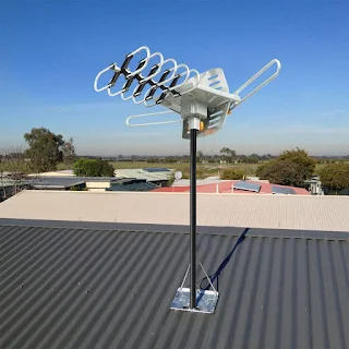
According to frequency range of the Digital TV Outdoor Antenna :

For Band VHF : 170 MHZ - 230 MHZ, Which is  television channels 7–13 (VHF-Hi), known as "Band III" internationally. A number of DTV channels have begun broadcasting here, especially many of the stations which were assigned to these channels for previous analog operation.

Digital TV Antenna OutdoorThe U.S. FCC allocated television broadcasting to a channelized roster as early as 1938 with 19 channels. That changed three more times: in 1940 when Channel 19 was deleted and several channels changed frequencies, then in 1946 with television going from 18 channels to 13 channels, again with different frequencies, and finally in 1948 with the removal of Channel 1 (analog channels 2-13 remain as they were

For Band UHF : 470 MHZ - 860 MHZ

    Australia

  • UHF citizens band(Land mobile service): 476–477 MHz
  • Television broadcasting uses UHF channels between 503 and 694 MHz
  • Canada

  • United Kingdom
  • Currently channels 21–35, 37 and 39–60 are used for Freeview digital TV.[6] Channel 36 is used for radar; channel 38 was used for radio astronomy but has been cleared to allow PMSE users access on a licensed, shared basis.
  • 791–862 MHz,[7] i.e. channels 61–69 inclusive were previously used for licensed and shared wireless microphones (channel 69 only), has since been allocated to 4G cellular communications.
  • United States
  • 470–512 MHz: Low-band TV channels 14–20 (shared with public safety land mobile 2-way radio in 12 major metropolitan areas scheduled to relocate to 700 MHz band by 2023[11])
  • 512–608 MHz: Medium-band TV channels 21–36
  • 608–614 MHz: Channel 37 used for radio astronomy and wireless medical telemetry[12]
  • 614–698 MHz: Mobile broadband shared with TV channels 38–51 auctioned in April 2017. TV stations will relocate by 2020. 

Specification of this Digital TV Antena Outdoor :
  •  Easy To Install : : Need common Tools set and Ladder if you have no access to roof , cabling path is easy to set , follow your house space wall.
    Digital TV Antenna Outdoor Mounting Installation at Roof House
  
What Purchaser said about this Antenna  ?


This Antenna Digital very Excellent for Outdoor use. You assembled the antenna by hand using the enclosed directions, easy no tools needed. Powered and tested the rotation/motor of the antenna in the house, worked as expected (didn’t use the remote as I didn’t have batteries, used the dock). Grabbed my ladder and tools with additional wood screws and washers as the package only contained 2 wood screws 
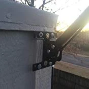
(not enough if you ask me). Climbed on to my roof and mounted the bracket on the side of my chimney tunnel exit than mounted the assembled antenna with pole. Ran the antenna’s coaxial cable down the side of my house and used a flat coaxial jumper cable to get it through my window seal into my house as I did not want to drill through my wall. Once I plugged in a second coaxial from the window flat jumper cable inside my house to the antenna power box and a third coaxial cable from the power box to my TV, I was in business... I troubleshooted the antenna rotation using our favorite channel that used to be fuzzy and studdered until I got great reception. The great news... once our favorite channel was in perfect reception, I used the settings on my TV to auto save all view able channels and now I have a TOTAL OF 54 CHANNELS (we live in Belton MO) that my family and I can watch!! That’s a win if you ask me. We had under 10 channels that stuttered before with our typical indoor antenna. Now to see how far it holds up and see how well it works during bad weather like rain and snow, not so sure if the material would hold up in Arizona sun but will be willing to try when we move back.

Another Purchaser commented :
I have tried many antennas, trying to get a TV station my wife wanted, and finally found it. Great antenna, easy to put together. I had a problem with the control box, but the customer service was great. I was very impress how quickly customer service answered all my questions and made sure I was happy with my purchase. I can receive 102 channels that is 2x more than all the other antennas I have tried. I even tried an antenna that cost about $200.00 bucks and this antenna is 2x better. I like that the antenna comes complete. Coax, pole. control box, remote. No extra wire is needed for the rotate function. Assembly is easy the antenna snaps together. Im a very picky guy, and do not normally give 5 stars, but this one really deserves it. I give the antenna a 5 star and the customer service was fantastic it also gets a 5 stars.


Not Sattisfied Purchaser commented about this Antenna :
 The service department was excellent. Quickly answered my email. We did some troubleshooting which did not correct the problem, so they sent me a new upgraded model at no extra charge. So far it is working fine. I would recommend bc if there is a problem the service team will take care of it promptly.
Original problem
WA 2608 150 mile range antenna. I have had my antenna hooked up 6 days. Assembly was easy. Installation instructions were clear. However after I installed it and used compass points to aim it, I ran a scan I did not pick up channels 65 miles away (per antenna point app and antennaweb), I did however get 29 channels from closer towers. Tried running scans at different times of the day and night to see if that effected anything bc a few of the channels would go in and out while watching a program. Then it just quit picking up any channels at all. Tried multiple scans but got zero channels. Emailing Service Team.