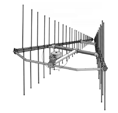
Antenna Theory - Log-periodic antenna - The Yagi-Uda antenna is mostly used for long time . However, for better reception and to tune over a range of frequencies, we need to have another antenna known as the Log-periodic antenna. A Log-periodic antenna with good impedance is a logarithamically periodic function of frequency.
A special type of directional antenna is the log-periodic dipole antenna (LPDA), where beam shaping is performed by means of several driven elements. The Log Periodic Dipole Antenna is made up of a number of parallel dipoles of increasing lengths and spacing (see Figure 26). Each dipole is fed out of phase to the element on either side by a common feed line. The angle α formed by the lines joining the dipole ends and by the longitudinal axis of the antenna remains constant, as well as the graduation factor 𝜏 which is equal to the ratio of the lengths of neighboring elements and their spacing:
This antenna type is characterized by its active and passive regions. The antenna is fed starting at the front (i.e. with the shortest dipole). The electromagnetic wave passes along the feed line and all dipoles that are markedly shorter than half a wavelength will not contribute to the radiation.
The dipoles in the order of half a wavelength are brought into resonance and form the active region, which radiates the electromagnetic wave back into the direction of the shorter dipoles.
This means that the longer dipoles located behind this active region are not reached by the electromagnetic wave at all. The active region usually comprises of 3 to 5 dipoles and its location obviously varies with frequency. The lengths of the shortest and longest dipoles of an LPDA-Log Periodic Dipole Antenna determine the maximum and minimum frequencies at which it can be used.
Due to the fact that at a certain frequency only some of the dipoles contribute to the radiation, the directivity (and therefore also the gain) that can be achieved with LPDAs-Log Periodic Dipole Antenna is relatively small in relation to the overall size of the antenna. However, the advantage of the LPDA is its large bandwidth which is - in theory - only limited by physical constraints.
The radiation pattern, of an LPDA is almost constant over the entire operating frequency range. In the H-plane it exhibits a half-power beamwidth of approx. 120°, while the E-plane pattern is typically 60° to 80° wide. The beamwidth in the H-plane can be reduced to values of approx. 65° by stacking two LPDAs in V-shape.
V-stacked LPDA antennas have E- and H-plane patterns with very similar half power beamwidths. Additionally they feature approx. 1.5 dB more gain compared to a normal LPDA.


,%20H-plane%20(blue).PNG)