Showing posts with label circuit. Show all posts

Adding A Driver / Amplifier for Increased Output Power


Addition o an RF power stage that you can use to extend your communications range. This part of the transmitter is arranged for class-A linear service. 

Although it is not necessary to use a linear amplifier for CW or FM amplification, there are some advantages : (1) a linear amplifier produces a lower level of harmonic currents; (2) it is easier to drive when a low-power stage is used to excite it. (3) the keyed waveform of the overall transmitter is less clicky than when using a class C amplifier after the keyed stage.

The Output power from Q2 is approximately 1 watt. This level of power will enable you to work DX when band conditions are good.

(source : W1FB Design Notebook)

150 mW CW Transmitter Circuit

A Schematic diagram of A 150 mW CW transmitter, Fixed value capacitors are disc ceramic , 50 V or greater , Resistors are 1/4 or 1/2 watt carbon film or carbon composition, C1 and C2 are feedback capacitors , C3 is a 10-100 pF ceramic or mica compression trimmer. 

A two circuit phone jack is used for J1 and an RCA phono connector or SO-239 coax connector may be used for J2, L1 is a 2.3 uH toroidal inductor. Use 24 turns of no. 26 enamel, wire on an Amidon T37-6 toroid core or other brand. L2 has three turns of no. 26 enamel, wire wound over the +12 V end of the L1 winding. 

Q1 is a 2N4400 or 2N4401 or equivalent transistor . A 2N2222A may be substituted, but will deliver less output power . Y1 is a fundamental crystal, 30 pF load capacitance.

(source : W1FB Design Notebook)

A Strobe flasher for bike indicator

Simple circuitry allows the project to be built at low cost in a lightweight, compact
package that can be secured to the bicycle or the rider's belt. 
The light from this circuit uses a xenon tube to generate a bright flash that can be
seen from a great distance - but is not intense enough to destroy a driver's night vision.

Circuit 


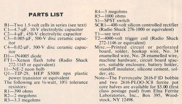
Parts Lists

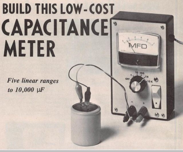
Build your own this low cost analog capacitance meter


When a capacitor is connected to a constant-voltage source through a resistor, the charge on the capacitor increases exponentially. If the source supplies a constant current, however the charge on the capacitor increases linearly. This linear charging principle is used here in the design of capacitance meter which will measure values outside the range of most such meters. 

By using a constant-current source, the meter determines the time it takes to match the charge on the unknown capacitor to a known reference voltage. The meter has five full scale range o 1, 10, 100, 1000, and 10,000 uF.on the 1-uF scale , values as small as 0.01 uF can be read easily.

The Circuit 


Power Supply


Parts List


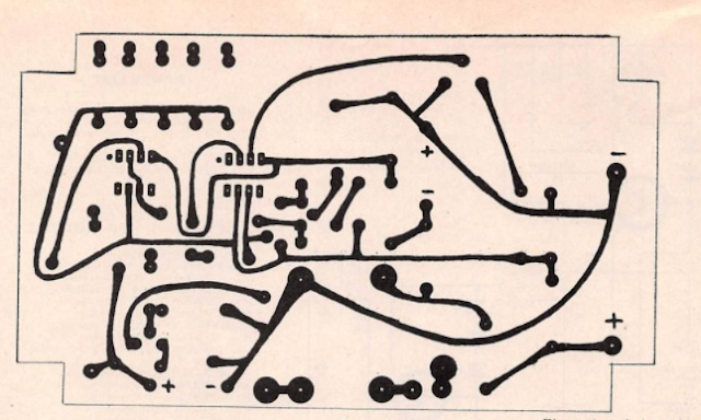
PCB Layout


Component Layout 


Prototype:


source :  Electronic Experimenters Handbook 1980 edition 

Loop Amplifier

Sharpening the loop 

Many years ago, the Q-multiplier was a popular add-on accessory for a communications receiver. These devices were sold as Heathkits, and many construction projects could be found in magazines and amateur radio books. 

The Q-multiplier has the effect of seeming to greatly increase the sensitivity of a receiver, as well as greatly reducing the bandwidth of the front end. Thus it allows better reception of some stations because of increased sensitivity and narrowed bandwidth. 

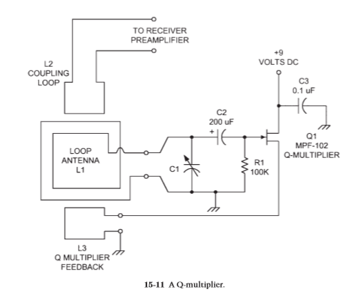
A Q-multiplier is an active electronic circuit placed at the antenna input of a receiver. It is essentially an Armstrong oscillator, as shown in Fig. 15-11, that does not quite oscillate. These circuits have a tuned circuit (L1/C1) at the input of an amplifier stage and a feedback coupling loop (L3). The degree of feedback is controlled by the coupling between L1 and L3. The coupling is varied by varying both how close the two coils are and their relative orientation with respect to each other.

Certain other circuits use a series potentiometer in the L3 side that controls the amount of feedback. The Q-multiplier is adjusted to the point that the circuit is just on the verge of oscillating, but not quite. As the feedback is backed away from the threshold of oscillation, but not too far, the narrowing of bandwidth occurs, as does the increase in sensitivity. It takes some skill to operate a Q-multiplier, but it is easy to use once you get the hang of it and is a terrific accessory for any loop antenna.

Loop amplifier 

Figure 15-12 shows the circuit for a practical loop amplifier that can be used with either shielded or unshielded loop antennas. It is based on junction field effect transistors (JFET) connected in cascade. The standard common-drain configuration is used for each transistor, so the signals are taken from the source terminals. The drain terminals are connected together and powered from the
12-V dc power supply.


A 2.2- F bypass capacitor is used to put the drain terminals of Q1 and Q2 at ground potential for ac signals while keeping the dc voltage from being shorted out. The two output signals are applied to the primary of a center-tapped transformer, the center tap of which is grounded. 

To keep the dc on the source terminals from being shorted through the transformer winding, a pair of blocking capacitors (C4, C5) is used. The input signals are applied to the gate terminals of Q1 and Q2 through dc blocking capacitors C2 and C3. A pair of diodes (D1, D2) is used to keep high-amplitude noise transients from affecting the operation of the amplifier. These diodes are connected back to back in order to snub out both polarities of signal. 

Tuning capacitor C1 is used in lieu of the capacitor in the loop and is used to resonate the loop to a specific frequency. Its value can be found from the equation given earlier. The transistors used for the push-pull amplifier (Q1, Q2) can be nearly any general-purpose JFET device (MPF-102, MPF-104, etc.). A practical approach for many people is to use transistors from service replacement lines, such as the NTE-312 and NTE-316 devices.

Wideband Active Loop Antenna for Shortwave band general purpose receivers

Active Wide band Loop Antenna for 10-30 MHz Band shortwave band you can construct in your home as Do It Yourself Project (Source article : Elektor Electronics Magazine).

Parts List :

PCB Design and component place :


Loop Antenna is a good indoor antenna alternative for a long wire antenna.


Crystal Tester Circuit


The circuit is use for test Quartz Crystal from 1 MHz to 50 MHz, if the crystal X1 good enough, sinewave will appears on Emiter T1 BF494 , and rectified by D2 IN4148 , drive D1 IN4148 and will charge Capacitor C4 until enough voltage to turn on Transistor BC547 and make the LED 1 on. This circuit using 9 V battery for enough consumption , below is PCB you can design . ( Source : Elektor Summer circuit)

Wideband Spark Transmissions Signal Receiver


This is circuit for Fun, receive spark transmissions signal from switch on off light , motors, high voltage lightning , electric motors can detected by this receiver on short wave band.

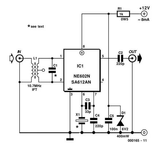
AM SW Converter with NE602

If you have old AM radio , you can use this circuit to change to Short Wave Radio, and tune the Short Wave frequency and start listening Short Wave around the world. The AM SW short wave radio can works from 1.6 MHz until 10 MHz by C1 with various values. from 150 pF until 10 pF , or you can use Trimmer Capacitor from 0-200 pF. For Crystals X1 can use 34.545 MHZ overtone crystal.


As datasheet NE602 describe , the features of this IC :

* Low current consumption : typical 2.4 mA
* Excellent noise figure : < 4.7 dB typical at 45 MHz
* High Operating frequency
* Excellent gain : intercept and sensitivity
* Low external parts count ; suitable for crystal / ceramics filter

NE602 Pin Out :


Test Configuration for NE602 , look at Crystal on Pin 6.


Applications :
* Portable Radio
* Cellular Radio

Example for Cellular Radio Application :

* VHF Transceivers
* RF Data Links
* HF / VHF Frequency conversion
* Instrumentation frequency conversion
* Broadband LANs


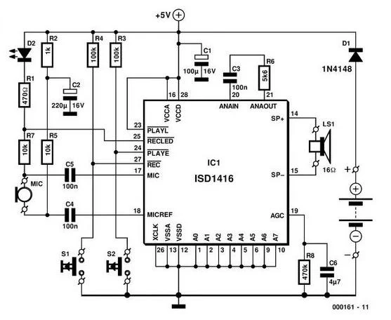
Voice Memory Circuit Using Single Chip ISD1416 from Winbond

Voice IC recording system memory , ISD1416 from Winbond can use for many application such Answering Machine Phone, Talking Clocks also for private application such as in Public Services to tell People How To use Toilet, private toilet by record instruction for 2 minutes.

The Features of ISD1416 :

* Easy to use single chip voice record/playback solution
* High quality, natural voice/audio reproduction
* Push button interface
   - Playback can be edge or level activated

* Single chip durations of 16 and 20 seconds
* Automatic power down mode
  - Enters standby mode immediately following a record or playback cycle
  - Standby current 0.5 uA (typical)
* Zero power message storage
  - Eliminates battery backup circuits
* Fully addressable to handle multiple messages
* 100 year message retention (typical)
* 100,000 record cycles (typical)
* On-chip clock source
* No programmer or development system needed
* Single +5 volt power supply
* Available in die form, DIP, and SOIC packaging
* Industriall temperature (-40 Celcius degree to +85 Celcius degree) versions available

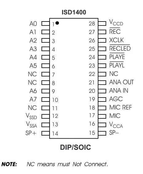
ISD 1400 Series Pinouts

 Application Note example from datasheet ISD1416


 For datasheet ISD1416 Please click here.


Simple Remote Control Tester

When your remote control  TV problems , because not works well , you can use this circuit to check .


This circuit using BP103 which is photo transistor who will response to infra red spectrum when remote control TV problem.
Transistor BC548 will biases and turn LED D1 will flash when you test your remote by pressing the button and make sure the infra red of remote works well. Check it Out!

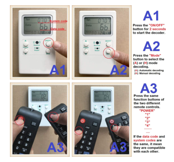
We have Generic Universal Tv Ir Remote Control Decoder Tester Infrared Remote Control Testing. with this tool you can answer the questions  :

(1)How to confirm different TV remote controls can be compatible with each other?
(2)My TV remote control doesn't work, if you don't have the one I need,which model can take place of it?


Use this to test functionality of the remotes before listing them. Super easy to use and does exactly what it is supposed to..

AM Longwave and Shortwave PC Radio

This circuit is Radio with 1 Transistor you can get supply for PC and listening from PC Speaker.

Source Elektor Electronic