Showing posts with label Kits. Show all posts

A Strobe flasher for bike indicator

Simple circuitry allows the project to be built at low cost in a lightweight, compact
package that can be secured to the bicycle or the rider's belt. 
The light from this circuit uses a xenon tube to generate a bright flash that can be
seen from a great distance - but is not intense enough to destroy a driver's night vision.

Circuit 


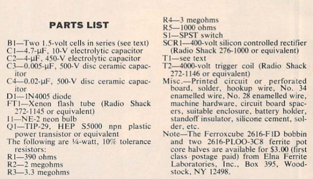
Parts Lists

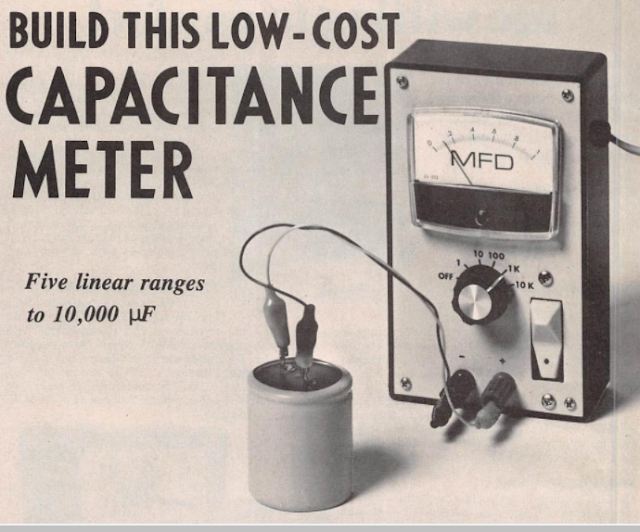
Build your own this low cost analog capacitance meter


When a capacitor is connected to a constant-voltage source through a resistor, the charge on the capacitor increases exponentially. If the source supplies a constant current, however the charge on the capacitor increases linearly. This linear charging principle is used here in the design of capacitance meter which will measure values outside the range of most such meters. 

By using a constant-current source, the meter determines the time it takes to match the charge on the unknown capacitor to a known reference voltage. The meter has five full scale range o 1, 10, 100, 1000, and 10,000 uF.on the 1-uF scale , values as small as 0.01 uF can be read easily.

The Circuit 


Power Supply


Parts List


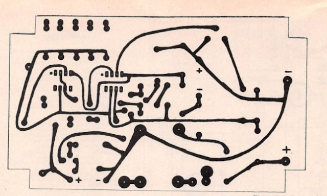
PCB Layout


Component Layout 


Prototype:


source :  Electronic Experimenters Handbook 1980 edition 

White LED Lamp Circuit

Make  this  solid-state pocket torch using a few of these white LEDs. The simplest approach is naturally to use a separate series resistor for each LED, which has an operating voltage of round 3.5 V at 20 mA. Depending on the value of the supply voltage, quite a bit of power will be lost in the resistors. 

The converter shown here generates a voltage that is high enough to allow ten LEDs to be connected in series. In addition this converter supplies a constant current instead of a constant voltage. 

A resistor in series with the LEDs produces a voltage drop that depends on the current through the LEDs. This voltage is compared inside the IC to a 1.25 V reference value, and the current is held constant at 18.4 mA ( 1.25V devided by 68Ohm)
The IC used is one of a series of National Semiconductor 'simple switchers'. The value of the inductor is not critical; it can vary by plus or minus 50 percent. 220 uH coil at 3.5 A is good choice. Almost any type of Schottky diode can also be used, as long as it can handle at least 1 A at 50 V. The zener diodes are not actually necessary but they are added to protect the IC. If the LED chain is opened during experiments, the voltage can rise to a value that the IC will not appreciate.

Circuit


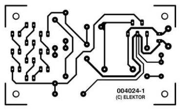
PCB Layout


Component Layout


Parts Lists


source ; Elektor 

DC Millivoltmeter with IC OP AMP 741

The Design of this DC Millivoltmeter presented here is a sensitive dc. electronic meter of several Megaohms input resistance and covering range from 5 Volt f.s.d to 5 mV f.s.d. 

This D.C. voltmeter designed to be used with 1 mA meter movement, this unit can be used as a pre-amplifier for a conventional test meter when switched to its 1 mA range for 5 V range. The range of meters from 5V f.s.d ,0.5V, 50mV, and 5mV f.s.d are provided, with input several Mega Ohm.


Build The Microcomputer SAP-1 (Continues 1)

As described in article before about the architecture of Microcomputer SAP-1 , in this article we will continue with other part of Microcomputer Diagram Block and circuit .
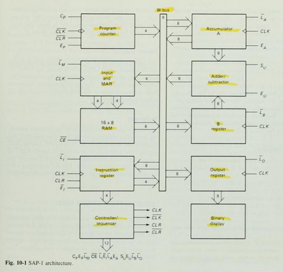
For you reference , in figure 10-1 as described  have Instruction Register, Accumulator, B Register, Output Register, and Binary Display, We will describe all about it in this article.


Instruction Register

The Instruction register is part of the control unit. to fetch an instruction from the memory the computer does a memory read operation. 

This places the contents of the addressed memory location on the W bus . At the same time, the instruction register is set up for loading on the next positive clock edge.

The contents of the instruction register are split into two nibbles. The upper nibble is a two-state output that goes directly to the block labeled "Controller sequencer". The lowe nibble is a three-state output that is read onto the W bus when needed.

Controller-Sequencer

The lower left block contains the controller-sequencer. Before each computer run, a Low CLR signal is sent to the program counter and a CLR signal to the instruction register.
 

Build The SAP-1 Microcomputer

This articles is from Book of Digital computer electronics : an introduction to microcomputers , book written by Albert Paul Malvino.

The SAP (Simple-As-Possible) computer has been designed for the beginner. The Main Purpose of SAP is to introduce all the crucial ideas behind computer operation without burying you in unnecessary detail. But even a simple computer like SAP covers many advanced concepts. to avoid bombarding you with too much all at once, we will examine three different generations of the SAP computer.

SAP-1 is the first stage in the evolution toward modern computers. Although primitive, SAP-1 is a big step for a beginner. So, dig into SAP-1, master SAP-1, its architecture, its programming , and its circuits, Then you will be ready for SAP-2. 

The Architecture 


Figure 10-1 shows the (structure) of SAP-1, a bus-organized computer. All register outputs to the W bus are three-state; this allows orderly transfer of data . All other register outputs are two-state; these outputs continuously drive the boxes they are connected to.

The layout of fig. 10-1  emphasizes the registers used in SAP-1. For this reason , no attempt has been made to keep all control circuits in one block called the control unit, all input-output circuits in another block called the I/O unit, etc.

many of registersof Fig. 10-1 are already familiar from earlier examples and discussions. What follows is a brief description of each box; detailed explanations come later.

The Circuit Diagram


Program Counter

The program is stored at the beginning of the memory with the first instruction at binary address 0000, the second instruction at address 0001, the third at address 0010, and so on. The program counter, which is part of the control unit, counts from 0000 to 1111. It is job is to send to the memory the address of the next instruction to be fetched and executed. It does this as follows.

The Program Counter is reset to 0000 before each computer run. When the computer run begins, the program counter sends address 0000 to the memory. The program counter is then incremented to get 0001. After the first instruction is fetched and executed, the program counter sends address 0001 to the memory. Again the program counter is incremented. After the second instruction is fetched and executed, the program counter sends address 0010 to the memory. In this way, the program counter is keeping track of the next instruction to be fetched and executed.

The program counter is like someone pointing a finger at a list of instructions, saying do this first, do this second, do this third, etc. This is why the program counter is sometimes callled a pointer; it points to an address in memory where something important is being stored. 


Input and MAR

Below the program counter is the input and MAR block. It includes the address and data switch registers. These Switch registers, which part of the input unit, allow you to send 4 address bits and 8 data bits to the RAM. As you recall, instruction and data words are written into the RAM before a computer run.

The Memory address register (MAR) is part of the SAP-1 memory. During a computer run, the address in the program counter is latched into the MAR. A bit later, the MAR applies this 4-bit address to the RAM, where a read operation is performed.

The RAM

The RAM is a 16 X 8 static TTL RAM. You can program the RAM by means of the address and data switch registers. This allows you to store a program and data in the memory before a computer run.
During a computer run, the RAM receives 4-bit addresses from MAR (Memory Address Register) and a read operation is performed, In this way , the instruction or data word stored in the RAM is placed on the W bus for use in some other part of the computer. 

On the next article, I will describe  Instruction register, controller sequencer, Accumulator/A Register, Adder/Subtractor, B Register, Output Register, and Binary Display.

DIY Six Stage Attenuator for High Frequency HF

If you have to deal with radio frequency more than very rarely, it is helpful if you can easily weaken the signals in discrete steps. 

So you can e.g. Bring the output signal of an HF generator to a different level than would only be possible with the generator's adjuster. 

There are many applications for a concealer when comparing or repairing receivers or with radio devices. Unfortunately, professional attenuator are quite expensive. 

Doing it yourself is worthwhile here because expensive electronics are not required
The Circuit Diagram of Six Stage Attenuator from Elektor Elektronic July Edition 2017 in Germany language 

Circuit Diagram


PCB Lay Out

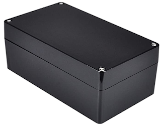
Final Six Stage Attenuator Prototype with aluminum case


With Six Stage Switches for 0..31 dB in 1 dB Step
Prototype Final

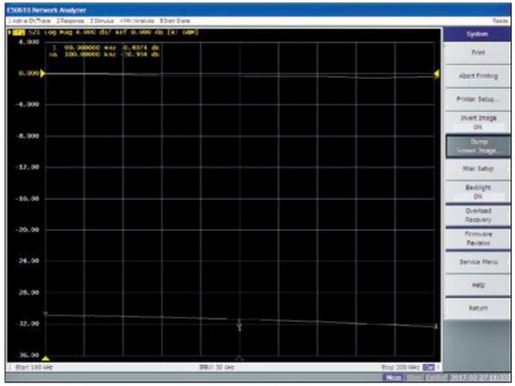
Frequency Response 0....-31 dB


Radio Straight or Crystal Radio for Science Project or Hobbyist


OA70 / IN34 / IN60 is Germanium Radio, choose only one type.
Antenna high from Ground is high is possible, ground is a must to Steel Water pipe, or making one from a piece of copper approximately 1 meter down to the ground, so will be voltage between ground and radio wave pick up by antenna.

I have build this Radio and connected input speaker to line input notebook and running with Open Lab software and can pick up Radio Signal from about 6 km air distance.

====+  Parts List for   +====

10 nF                              1   Capacitor


VC 500 pF                      1   Variable Capacitor


OA70/IN34/IN60             1


 GND                               1   GND
Termination Ground

108 Turns,12 Turns        L Tap between 108 Turns and 12 Turns

8-2000 Ohm  1   SPKR or Earphone 8 - 2000 Ohm , you can get this in junk shop or at ebay.com

RF Connector Male and Female For Antenna Connection
 

50 Ohm Coaxial cable for Antenna


Electronic Project Box


Antenna for LW,MW,SW and AM 

Voice Memory Circuit Using Single Chip ISD1416 from Winbond

Voice IC recording system memory , ISD1416 from Winbond can use for many application such Answering Machine Phone, Talking Clocks also for private application such as in Public Services to tell People How To use Toilet, private toilet by record instruction for 2 minutes.

The Features of ISD1416 :

* Easy to use single chip voice record/playback solution
* High quality, natural voice/audio reproduction
* Push button interface
   - Playback can be edge or level activated

* Single chip durations of 16 and 20 seconds
* Automatic power down mode
  - Enters standby mode immediately following a record or playback cycle
  - Standby current 0.5 uA (typical)
* Zero power message storage
  - Eliminates battery backup circuits
* Fully addressable to handle multiple messages
* 100 year message retention (typical)
* 100,000 record cycles (typical)
* On-chip clock source
* No programmer or development system needed
* Single +5 volt power supply
* Available in die form, DIP, and SOIC packaging
* Industriall temperature (-40 Celcius degree to +85 Celcius degree) versions available

ISD 1400 Series Pinouts

 Application Note example from datasheet ISD1416


 For datasheet ISD1416 Please click here.


AM Longwave and Shortwave PC Radio

This circuit is Radio with 1 Transistor you can get supply for PC and listening from PC Speaker.

Source Elektor Electronic