The delta loop antenna, like the Greek uppercase letter “delta” (∆) from which it draws its name, is triangle-shaped (Fig. 14-8). The delta loop is a full wavelength, with elements approximately 2 percent longer than the natural wavelength (like the quad). The actual length will be a function of the proximity and nature of the underlying ground, so some experimentation is necessary. The approximate preadjustment lengths of the sides are found from:
The delta loop antenna is fed from 52-Ωcoaxial cable through a 4:1 balun transformer. The delta loop can be built in a fixed location, and will offer a bidirectional pattern.
Reference : Practical Antenna Handbook - by Joseph J. Carr
Complete free tutorial antennas design , diy antenna , booster antenna, filter antenna , software antenna , free practical antenna book download !
Demiquad Loop Antenna
1 Lambda Large Loops
If size is not forcing you to a /2 loop, then a 1 loop might be just the ticket. It produces a gain of about
2 dB over a dipole in the directions that are perpendicular to the plane of the loop. The azimuth patterns formed by these antennas are similar to the figure-8 pattern of the dipole. Three versions are shown: the square loop (Fig. 14-3), the diamond loop (Fig. 14-4), and the delta loop (a.k.a. D-loop and triangle—Fig. 14-5). The square and diamond loops are built with /4 on each side, and the delta loop is /3 on each side. The overall length of wire needed to build these antennas is
The polarization of the three loop antennas is horizontal, because of the location of the feedpoints. On the square loop, moving the feedpoint to the middle of either vertical side will provide vertical polarization. Similarly, on the diamond loop vertical polarization is realized by moving the feedpoint to either of the two adjacent apexes. On the delta loop, placing the feedpoint at either of the two other apexes produces a diagonal polarization that offers approximately equal vertical and horizontal polarization components.
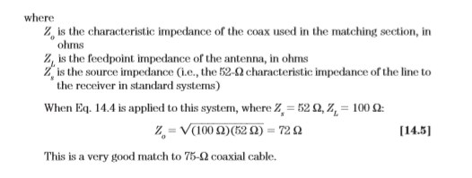
The feedpoint impedance of the 1 loop is around 100 Ω, so it provides a slight mismatch to 75-Ωcoax and a 2:1 mismatch to 52-Ωcoax. A very good match to 52-Ω coax can be produced using the scheme of Fig. 14-6. Here, a quarter-wavelength coaxial cable matching section is made of 75-Ω coaxial cable. The length of this cable should be
From Book : Practical Antenna Handbook - By Joseph J. Carr
Large wire loop antennas
THERE ARE TWO BASIC FORMS OF LOOP ANTENNAS: SMALL AND LARGE. THESE TWO TYPES have different characteristics, work according to different principles, and have different purposes. Small loops are those in which the current flowing in the wire has the same phase and amplitude at every point in the loop (which fact implies a very short wire length, i.e., less than 0.2 ). Such loops respond to the magnetic field component of the electromagnetic radio wave. A large loop antenna has a wire length greater than 0.2 , with most being either /2, 1 , or 2 . The current in a large loop varies along the length of the wire in a manner similar to other wire antennas.
Lambda/2 large loops
The performance of large wire loop antennas depends in part on their size. Figure 14-1 shows a half-wavelength loop (i.e., one in which the four sides are each /8 long). There are two basic configurations for this antenna: continuous (S1 closed) and open (S1 open). In both cases, the feedpoint is at the midpoint of the side opposite the switch. The direction of the main reception, or radiation lobe (i.e., the direction of maximum reception), depends on whether S1 is open or closed. With S1 closed, the main lobe is to the right (solid arrow); and with S1open, it is to the left (broken arrow). Direction reversal can be achieved by using a switch (or relay) at S1, although some people opt for unidirectional operation by eliminating S1, and leaving the loop either open or closed. The feedpoint impedance is considerably different in the two configurations. In the closed-loop situation (i.e., S1 closed), the antenna can be modeled as if it were a half-wavelength dipole bent into a square and fed at the ends. The feedpoint (X1 X2) impedance is on the order of 3 kΩ because it occurs at a voltage antinode (current node). The current antinode (i.e., Imax) is at S1, on the side opposite the feedpoint. An antenna tuning unit (ATU), or RF impedance transformer, must be used to match the lower impedance of the transmission lines needed to connect to receivers. The feedpoint impedance of the open-loop configuration (S1 open) is low because the current antinode occurs at X1 X2. Some texts list the impedance as “about 50 Ω,” but my own measurements on several test loops were somewhat higher (about 70 Ω). In either case, the open loop is a reasonable match for either 52- or 75-Ωcoaxial cable.
Neither Lambda/2 loop configuration shows gain over a dipole. The figure usually quoted is 1-dB forward gain (i.e., a loss compared with a dipole), and about 6-dB front-to-back ratio (FBR). Such low values of FBR indicate that there is no deep notch (“null”) in the pattern. A lossy antenna with a low FBR seems like a born loser, and in most cases it is. But the /2 loop finds a niche where size must be constrained, for one reason or another. In those cases, the /2 loop can be an alternative. These antennas can be considered limited-space designs, and can be mounted in an attic, or other limitedaccess place, as appropriate. A simple trick will change the gain, as well as the direction of radiation, of the closed version of the /2 loop. In Fig. 14-2, a pair of inductors (L1 and L2) are inserted into the circuit at the midpoints of the sides adjacent to the side containing the feedpoints. These inductors should have an inductive reactance XL of about 360 Ω in the center of the band of operation. The inductance of the coil is
The coils force the current antinodes toward the feedpoint, reversing the direction of the main lobe, and creating a gain of about
1 dB over a half-wavelength dipole. The currents flowing in the antenna can be quite high, so when making the coils, be sure to use a size that is sufficient for the power and current levels anticipated. The 2- to 3-in B&W Air-Dux style coils are sufficient for most amateur radio use. Smaller coils are available on the market, but their use is limited to low-power situations.
Build Phasing Transformer Antenna
A directional antenna has the ability to enhance reception of desired signals, while rejecting undesired signals arriving from slightly different directions. Although directivity normally means a beam antenna, or at least a rotatable dipole, there are certain types of antenna that allow fixed antennas to be both directive and variable. See Chap. 7 for fixed but variable directional antennas and Chap. 11 for fixed and non-variable directive arrays. Those antennas are transmitting antennas, but they work equally well for reception. This section shows a crude, but often effective, directional antenna that allows one to select the direction of reception with pin plugs or switches.
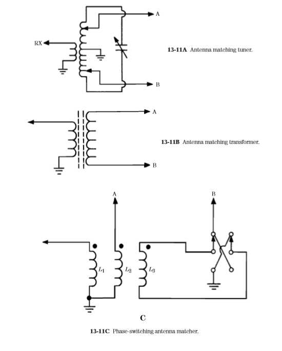
Consider Fig. 13-10. In this case, a number of quarter-wavelength radiators are fanned out from a common feedpoint at various angles from the building. At the near end of each element is a female banana jack. A pair of balanced feedlines from the receiver (300-Ω twin lead, or similar) are brought to the area where the antenna elements terminate. Each wire in the twin lead has a banana plug attached. By selecting which banana jack is plugged into which banana plug, you can select the directional pattern of the antenna. If the receiver is equipped with a balanced antenna input, then simply connect the other end of the twin lead direction to the receiver. Otherwise, use one of the couplers shown in Fig. 13-11.
Figure 13-11A shows a balanced antenna coupler that is tuned to the frequency of reception. The coil is tuned to resonance by the interaction of the inductor and the capacitor. Antenna impedance is matched by selecting the taps on the inductor to which the feedline is attached. A simple RF broadband coupler is shown in Fig. 13-11B. This transformer is wound over a ferrite core, and consists of 12 to 24 turns of no. 26 enameled wire, with more turns being used for lower frequencies, and fewer for higher frequencies. Experiment with the number of turns in order to determine the correct value. Alternatively, use a 1:1 balun transformer instead of Fig. 13-11B; the type intended for amateur radio antennas is overkill powerwise, but it will work nicely.
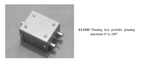
The antenna of Fig. 13-10 works by phasing the elements so as to null, or enhance (as needed), certain directions. This operation becomes a little more flexible if you build a phasing transformer, as shown in Fig. 13-11C and 13-11D. Windings L1, L2, and L3 are wound “trifilar” style onto a ferrite core. Use 14 turns of no. 26 enameled wire for each winding. The idea in this circuit is to feed one element from coil L2 in the same way all of the time. This port becomes the 0° phase reference. The other port, B, is fed from a reversible winding, so it can either be in phase or 180°out of phase with port A. Adjust the DPDT switch and the banana plugs of Fig. 13-10 for the best reception.
Subscribe to:
Comments (Atom)


