Half Delta Sloper (HDS) Antenna

The half-delta sloper (HDS) antenna (Fig. 14-9) is similar to the full delta loop, except that (like the quarter-wavelength vertical) half of the antenna is in the form of an “image” in the ground. Gains of 1.5 to 2 dB are achievable. The HDS antenna consists of two elements: a /3-wavelength sloping wire and a /6 vertical wire (on an insulated mast), or a /6 metal mast. 

Because the ground currents are very important, much like the vertical antenna, either an extensive radial system at both ends is needed, or a base ground return wire (buried) must be provided. The HDS will work on its design frequency, plus harmonics of the design frequency. For a fundamental frequency of 5 MHz, a vertical segment of 33 ft and a sloping section of 66 ft is needed. The lengths for any frequency are found from


The HDS is fed at one corner, close to the ground. If only the fundamental frequency is desired, then you can feed it with 52-Ω coaxial cable. But at harmonics, the feedpoint impedance changes to as high as 1000 Ω. If harmonic operation is intended, then an antenna tuning unit (ATU) is needed at point A to match these impedances.

Bisquare Loop Antenna

The bisquare antenna -  The bisquare antenna offers as much as 4-dB gain broadside to the plane of the antenna (i.e., in and out of the book page), in a figure-8 pattern, on the design frequency. It is horizontally polarized. When the frequency drops to one-half of the design frequency, the gain drops to about 2 dB, and the antenna works like the diamond loop covered previously.shown in Fig. 14-10, is similar to the other large loops, except that it is /2 on each side, making a total wire length of two wavelengths. This antenna is built like the diamond loop shown earlier (i.e., it is a large square loop fed at an apex that is set at the bottom of the assembly). In this case, the loop is fed either with an antenna tuning unit (to match a 1000-Ωimpedance) or a quarter-wavelength matching section made of 300-Ω or 450-Ω twin-lead transmission line. A 1:1 balun transformer connects the 75-Ω coaxial cable to the matching section. the bi-square is not quite a real loop since it is split at the top.

The bi-square antenna offers as much as 4-dB gain broadside to the plane of the antenna (i.e., in and out of the book page), in a figure-8 pattern, on the design frequency. It is horizontally polarized. When the frequency drops to one-half of the design frequency, the gain drops to about 2 dB, and the antenna works like the diamond loop covered previously.
For bi-square Antenna many prefer use coaxial cable to the 300 ohm ribbon feedline to the bi-square normally uses.


If you think a single element quad loop (1 wavelength perimeter) is large, double its size to get an idea of the bi-square's dimensions.  But despite what it looks like from a far, the bi-square is not quite a real loop since it is split at the top.

Still, if you have one tall tower (at least 3/4 wavelength high) the bi-square may be worth considering. It's basically a bidirectional gain antenna. If you've already got the wire the construction cost is low. And you may be able to use some ingenious remote switching with relays to change the antenna into a large loop for other bands. 

1/4 Lambda Bi-Square Antenna

Another example project The Bi-Square antenna with four half-waves in phase, which makes it three half-waves and about 4 db better than dipole. The Bi-square to be described  is for 15 meters , also success used for 20m and 40m band.
The advantages of this antenna are many. It's cheap , you need only one pole, 35 feet or over, to hang it on. It is bi-directional . you can hang two of them on one pole and cover 360 degrees. It's easy to tune. It has 4 dB Gain, which puts it in the well tuned two-element beam class. It is also good competition for the "pre-tuned" or untuned three-element beam. This Bi-square antenna can feed in to 150 watt Sideband Transmitter.

Reference : Practical Antenna handbook - Joseph J. Carr
                    Antenna Magazine

Delta loop Antenna

The delta loop antenna, like the Greek uppercase letter “delta” (∆) from which it draws its name, is triangle-shaped (Fig. 14-8). The delta loop is a full wavelength, with elements approximately 2 percent longer than the natural wavelength (like the quad). The actual length will be a function of the proximity and nature of the underlying ground, so some experimentation is necessary. The approximate preadjustment lengths of the sides are found from:


The delta loop antenna is fed from 52-Ωcoaxial cable through a 4:1 balun transformer. The delta loop can be built in a fixed location, and will offer a bidirectional pattern.

Reference : Practical Antenna Handbook - by Joseph J. Carr

Demiquad Loop Antenna

The demiquad is a single-element 1 quad antenna. The length of the antenna is, like the cubical quad beam antenna (see Chap. 12), one wavelength. Figure 14-7 shows a type of demi-quad based on the tee-cross type of mast. The impedance-matching section is a quarter-wavelength piece of 75-Ω coaxial cable (RG-58/U or RF-11/U). The length of the matching section is determined from:


1 Lambda Large Loops

If size is not forcing you to a /2 loop, then a 1 loop might be just the ticket. It produces a gain of about
2 dB over a dipole in the directions that are perpendicular to the plane of the loop. The azimuth patterns formed by these antennas are similar to the figure-8 pattern of the dipole. Three versions are shown: the square loop (Fig. 14-3), the diamond loop (Fig. 14-4), and the delta loop (a.k.a. D-loop and triangle—Fig. 14-5). The square and diamond loops are built with /4 on each side, and the delta loop is /3 on each side. The overall length of wire needed to build these antennas is


The polarization of the three loop antennas is horizontal, because of the location of the feedpoints. On the square loop, moving the feedpoint to the middle of either vertical side will provide vertical polarization. Similarly, on the diamond loop vertical polarization is realized by moving the feedpoint to either of the two adjacent apexes. On the delta loop, placing the feedpoint at either of the two other apexes produces a diagonal polarization that offers approximately equal vertical and horizontal polarization components.

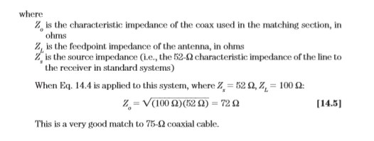
The feedpoint impedance of the 1 loop is around 100 Ω, so it provides a slight mismatch to 75-Ωcoax and a 2:1 mismatch to 52-Ωcoax. A very good match to 52-Ω coax can be produced using the scheme of Fig. 14-6. Here, a quarter-wavelength coaxial cable matching section is made of 75-Ω coaxial cable. The length of this cable should be

From Book : Practical Antenna Handbook - By Joseph J. Carr