Style Social Media Buttons

Quad Beam Antennas

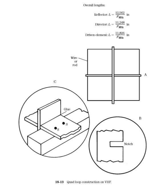
The quad antenna was introduced in the chapter on beams. It is, nonetheless, also emerging as a very good VHF/UHF antenna. It should go without saying that the antenna is a lot easier to construct at VHF/UHF frequencies than it is at HF frequencies! Figure 18-13 shows a modest example. 

There are several methods for building the quad antenna, and Fig. 18-13 represents only one of them. The radiator element can be any of several materials, including heavy solid wire (no. 8 to no. 12), tubing, or metal rods. The overall lengths of the elements are given by:


There are several alternatives for making the supports for the radiator. Because of the lightweight construction, almost any method can be adapted for this purpose.

 In the case shown in Fig. 18-13, the spreaders are made from either 1-in furring strips, trim strips, or (at above 2 m) even wooden paint stirring sticks. The sticks are cut to length, and then half-notched in the center (Fig. 18-13, detail B). 

The two spreaders for each element are joined together at right angles and glued (Fig. 18-13, detail C). The spreaders can be fastened to the wooden boom at points S in detail C. The usual rules regarding element spacing (0.15 to 0.31 wavelength) are followed. 

See the information on quad antennas in Chap. 12 for further details. Quads have been successfully built for all amateur bands up to 1296 MHz.


Halo Antennas

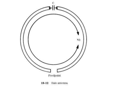
One of the more saintly antennas used on the VHF boards is the halo (Fig. 18-12). This antenna basically takes a half-wavelength dipole and bends it into a circle. 

The ends of the dipole are separated by a capacitor. In some cases, a transmitting-type mica “button” capacitor is used, but in others (and perhaps more commonly), the halo capacitor consists of two 3-in disks separated by a plastic dielectric. 

While air also serves as a good (and perhaps better) dielectric, the use of plastic allows mechanical rigidity to the system.

Groundplane Antennas


The groundplane antenna is a vertical radiator situated above an artificial RF ground consisting of quarter-wavelength radiators. Groundplane antennas can be either 1⁄4-wavelength or 5⁄8-wavelength (although for the latter case impedance matching is needed—see the previous example).

Figure 18-11 shows how to construct an extremely simple groundplane antenna for 2 m and above. The construction is too lightweight for 6-m antennas (in general), because the element lengths on 6-m antennas are long enough to make their weight too great for this type of construction. The base of the antenna is a single SO-239 chassis-type coaxial connector. Be sure to use the type that requires four small machine screws to hold it to the chassis, and not the single-nut variety.

The radiator element is a piece of 3⁄16-in or 4-mm brass tubing. This tubing can be bought at hobby stores that sell airplanes and other models. The sizes quoted just happen to fit over the center pin of an SO-239 with only a slight tap from a lightweight hammer—and I do mean slight tap. If the inside of the tubing and the connector pin are pretinned with solder, then sweat soldering the joint will make a good electrical connection that is resistant to weathering. Cover the joint with clear lacquer spray for added protection.


The radials are also made of tubing. Alternatively, rods can also be used for this purpose. At least four radials are needed for a proper antenna (only one is shown in Fig. 18-11). This number is optimum because they are attached to the SO-239 mounting holes, and there are only four holes. Flatten one end of the radial, and drill a small hole in the center of the flattened area. Mount the radial to the SO-239 using small hardware (4-40, etc.).

The SO-239 can be attached to a metal L bracket. While it is easy to fabricate such a bracket, it is also possible to buy suitable brackets in any well-equipped hardware store. While shopping at one do-it-yourself type of store, I found several reasonable candidate brackets. The bracket is attached to a length of 2 2-in lumber that serves as the mast.

J Pole Antennas

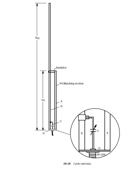
The J-pole antenna is another popular form of vertical on the VHF bands. It can be used at almost any frequency, although the example shown in Fig. 18-10 is for 2 m. The antenna radiator is 3⁄4-wavelength long, so its dimension is found from

Taken together the matching section and the radiator form a parallel transmission line with a characteristic impedance that is 4 times the coaxial cable impedance. If 50-Ω coax is used, and the elements are made from 0.5 in OD pipe, then a spacing of 1.5 in will yield an impedance of about 200 Ω. Impedance matching is accomplished by a gamma match consisting of a 25-pF variable capacitor, connected by a clamp to the radiator, about 6 in (experiment with placement) above the base.

5/8 Wavelength Antenna for 2 m Mobile Radio


The 5⁄8-wavelength antenna (Fig. 18-9) is popular on 2 m for mobile operation because it is easy to construct, and it provides a small amount of gain relative to a dipole. The radiator element is 5⁄8-wavelength, so its physical length is found from:

The 5⁄8-wavelength antenna is not a good match to any of the common forms of coaxial cables. Either a matching section of cable, or an inductor match, is normally used. In Fig. 18-9 an inductor match is used. The matching coil consists of 2 to 3 turns of no. 12 wire, wound over a 1⁄2-in OD form, 1⁄2-in long. The radiator element can be tubing, brazing rod, or a length of heavy “piano wire.” Alternatively, for low-power systems, it can be a telescoping antenna that is bought as a replacement for portable radios or televisions. These antennas have the advantage of being adjustable to resonance without the need for cutting.