5 Best Satellite Phones for backpacking of 2022 (buyers guide) - We’ll walk you through the perks and drawbacks of the best satellite phones for backpacking on the market so you can find the sat phone that will be ready when you need it the most.
With the increasing coverage area of satellite phones communicator providers, from Globalstar, Iridium, Inmarsat, Thuraya, it makes it easier for clients to have better communication in remote areas, such as mountains, hills, forests, oceans and areas that cannot be reached by cellular communications, common Wi-Fi networks, can currently be reached by telephone communications and satellite data, by interconnect Satellite Constellation with terrestrial Telecommunication. Now, Remote Industrial such Oil & Gas, Mining Company, Marine and Backpackers who have high mobility in Outdoor activity to the remote area, can stay connected and safe anywhere with the service from all Satellite Phones provider anywhere
No Hidden Fees, No Roaming Charges
Specs
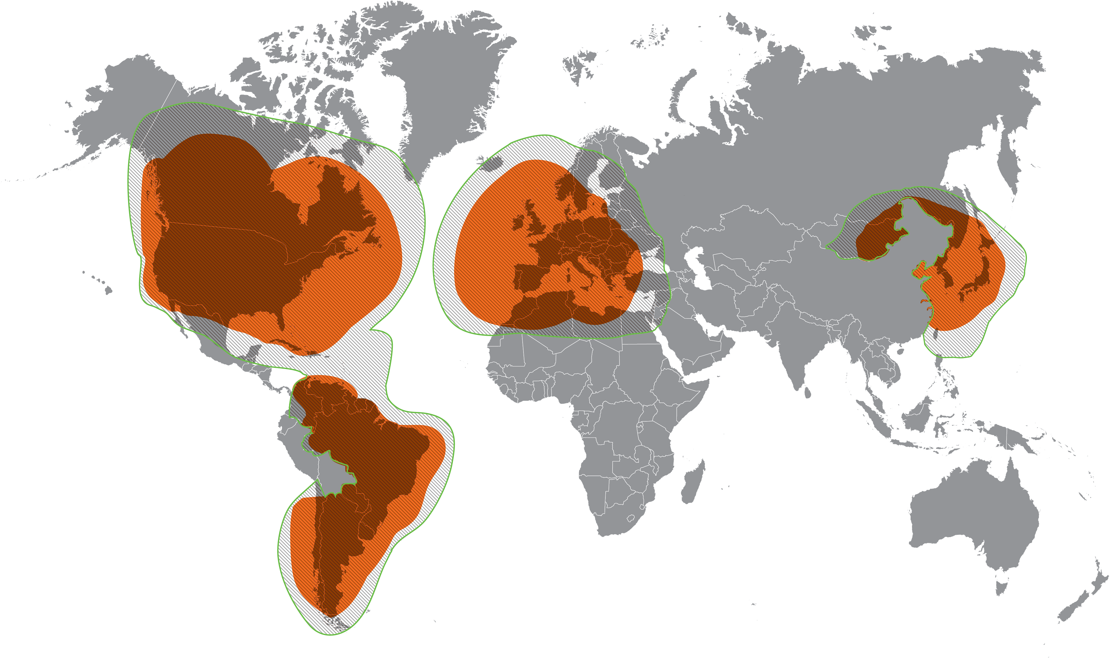
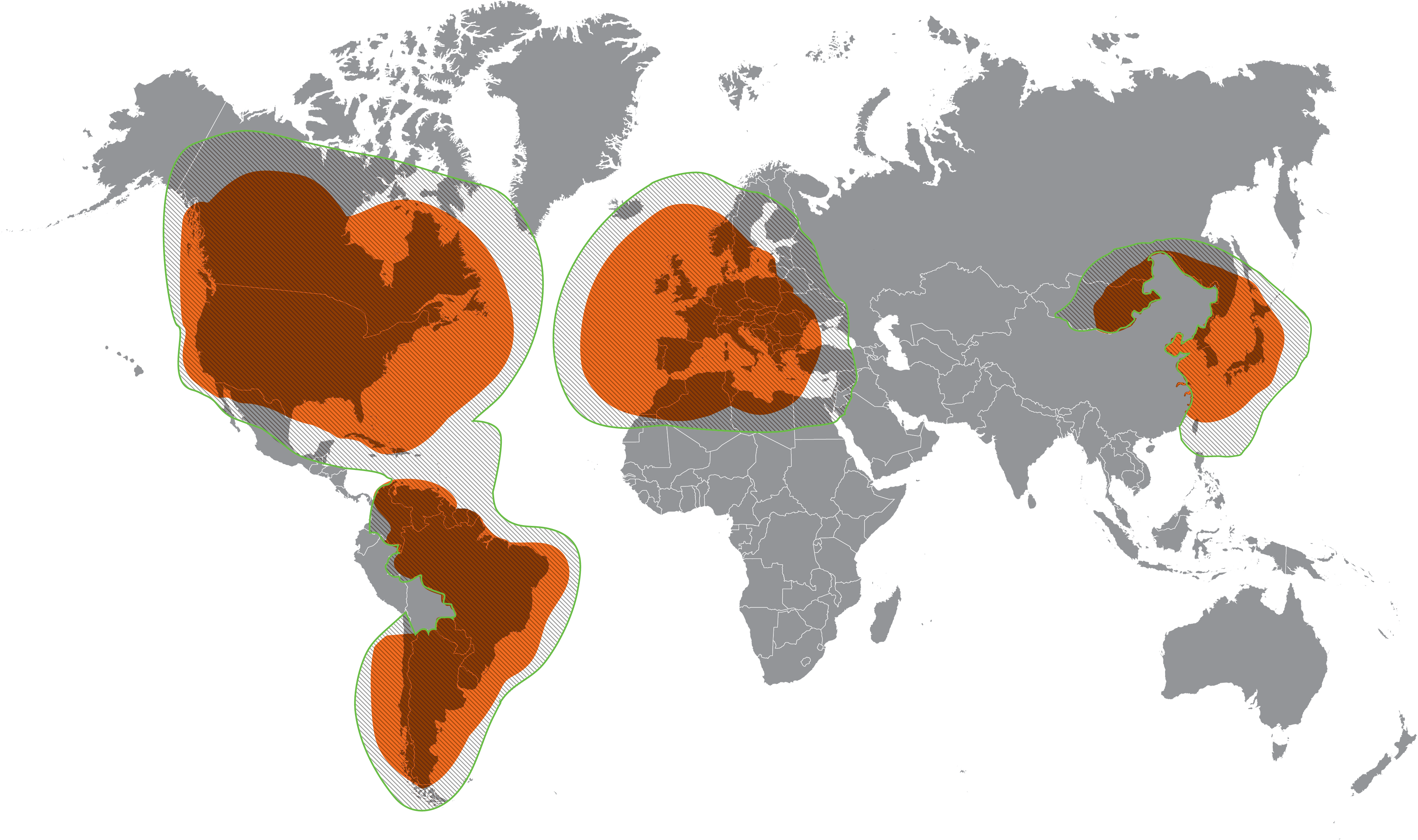
Network Coverage: Global with reduced coverage in the extreme North or South
Inmarsat's 5th generation of satellites provides network coverage wherever you go.
With 13 geostationary satellites up in the air, each covers up to one-third of the Earth’s surface, and coverage extends from latitudes* of approximately -82° to 82°, letting you enjoy voice and data communications almost anywhere on Earth.
Constellation: 13 Geostationary satellites, Inmarsat owns and operates 13 satellites in geostationary orbit 35,786km (22,236 miles) above the Earth.
Location Based Service : Yes
SOS Included : Yes
Durability : IP65 and IK04 resistant
Battery Life : 8 hrs talk time; 160 hrs standby
Weight : 318 g (11.2 oz)
Dimensions : 6.7 x 3 x 1.14"
Rating : 4.3/5
Pros : No Hidden Fees, No Roaming
Cons : Coverage extends from latitudes -82 to 82 degree of the globe
More Information Video of Inmarsat Isatphone 2.1
Specs
Network Coverage : Global, Pole to Pole
The Low-Earth Orbit Advantage
At only 476 miles (780 km) from the Earth, the proximity of
Iridium’s LEO network means pole-to-pole coverage, a shorter
transmission path, stronger signals, lower latency and shorter
registration time than with GEO satellites.
Constellation : 66 Lower Earth Orbit Satellites
GPS enabled Location-based service : Yes, Online Tracking
SOS Included : Yes, Satellite Emergency Notification Device (SEND) Compliant SOS button design
Durability : Mil-STD 810F and Ingress Protection rating of IP65 , military Grade, Rugged
Battery Life : 4 hrs talk time; 30 hrs standby
Weight : 247 g (8.7 oz)
Dimensions : 5.5 x 2.4 x 1.06"
Another Features : Shock resistant, water jet resistant, dust proof.
Rating : 4.2/5
Pros : Wide Coverage from South Pole to North Pole
Cons : Talk time battery life 4 hrs
More information Video for Iridium Extreme
Specs
Certified Refurbished Phone Satellite
Network Coverage : Using Low earth Orbit (LEO) Satellites
Constellation : 24 Leo Satellites interconnection with terrestrial telecommunication infrastructure
Voice & Data : No Voice Delay, Data speed 9,6KBps uncompressed data, and 38.6 KBps compressed data (need 9600 hotspot, sold separately)
SOS : for U.S based phone number Direct Dialing 911 services
GPS : Yes
Battery Life : Talk time 3.75 hours ,and standby time 19 hours
Weight : 384 gr
Dimensions : 6.97" x 2.24" x 1.89"
Rating : 4.1/5
Services :
Voice Mail
Call Forwarding
Short Message System (SMS)
Roaming & Long Distance
Display Position Location Information
Data Network Services :
By Connecting GSP-1600 to Globalstar 9600 (GDK-9600) customer can used their existing Wi-Fi enabled devices, such as smartphones, tablets, and laptops to send and receive emails.
Data speeds compressed up to 38.6 Kbps (uncompressed speed 9.6 Kbps)
Easily send and receive emails and post to social media from any WiFi enabled device
No Additional cost , by using existing Globalstar airtime plan minutes
WiFi range up to 30 ft
RF Power Output Phone GSP 1600 : +/- 26 dBm and +/- 29.5 dBm in using Car Kit.
Pros : The Cheapest Satellite Phone
Cons : Need buy Globalstar 900 Hostspot for accessing WiFi
Here is Video Globalstar services included GSP 1600
Android OS Satellite & GSM Phone with Dual SIM
Specs
Network Coverage : Across Europe, Africa, Asia, Australia, and America with several roaming partners
This map represents Thuraya expectations of Satellite Network Coverage, for further information please contact Thuraya Customer Care
This Map represents Thuraya expectations of GSM Coverage Roaming, for further information please contact Thuraya customer care.
Constellation : 5 Geostationary Satellite from Yahsat.
Since first Satellite in April 2011 Yahsat acquired Thuraya and joint ventures with Hughes , and operate 5 Satellite and a reach spreading across more than 160 countries.
You can look Elevation and Azimuth Yahsat Satellite based on your country by using the Look Angle Calculator from Yahsat. For example the elevation and azimuth Satellite Al Yah1 from Seoul, South Korea. You can entering in search box for another country.
GPS Enabled location-based service: Yes, GPS, BeiDou, Glonass systems for highest flexibility in all regions
Operating System : Android Nougat 7.1.2
SOS Included : Yes, even phone in Switched Off Position, if you press SOS button and hold for 3 seconds , will start the handsets and triggers the SOS Call/SMS to pre programmed number.
Battery Life : Talk Time 10 hours, standby time 100 hours
Another Feature : Since the Thuraya X5 Touch phone used Google Android as platform, make user more free customize and personalize the phone to their needs (BYOA - Bring Your Own App). User can download from Google Play store from third party developer. Also Thuraya X5 Touch can easily integrates with wearables technology like Smartwatches, health care wearable , etc.
Weight : 262 g
Dimensions : 145 X 78 X 24 mm
Pros : Coverage Satellite and GSM Phone, Android OS Nougat 7.1.2
5.2" Full HD Touchscreen made from Gorilla(TM) Glass from Corning.
Cons : Roaming Charges in USA and several countries
Rating : 4.8/5
More information Video Thuraya X5 Touch
Network Coverage :  Primary Coverage,
  Fringe Coverage, Customers will expected weak signal ,
  Home Zone Coverage, Customer in North America can freely roam without incurring additional airtime costs
Constellation : 24 Low Earth Orbit (LEO) Satellite and traditional infrastructure on six continents serving for more than 120 countries
Battery Life : Talk time 4 hours, standby 36 hours
GPS enabled-location based service : Yes
SOS Included : Yes ,by dial to GEOS for Satellite Emergency Notification Device (S.E.N.D), by dialing 1+ Area Code + Phone Number to International Emergency Response Coordination Center (IERCC), You can find more information on Geosresponse.com, GEOS have coordination with Search And Rescue Agencies around the Globe.
Weight : 1 pounds
Dimensions : 8 x 8 x 2 inches
Rating : 2/5
Pros : SOS signal send to S.A.R Agencies around the globe with coordination International Emergency Response Coordination (IERCC)
Cons : Roaming Airtime in Outside US
More information Video for Globalstar GSP-1700