Comparison Long Range tv antenna for rural areas : GE Outdoor TV Antenna VS Antennas Direct Outdoor Antenna

Rural areas consist of savanna , mountain, trees, with hilly land , far away from Broadcasting TV Tower and need Antenna TV Outdoor/Indoor with High Gain for reach the signal from the TV transmitting tower.


With todays many cellular tower in the rural areas, and affect TV signal reception , we also need cellular filter 3G/4G/5G.

For this purpose I will compare GE Outdoor TV Antenna VS Antennas Direct Outdoor Antenna with keys criteria for you as reference.

If you live in USA and Canada please check your coverage in FCC website. 

Check Coverage

Use dtv reception maps   to check for the DTV signals that are available at your location. Enter your address in the box at dtv reception maps and click Go! The DTV coverage map will list all stations in your area.

Sometimes stations change the frequency on which they broadcast — the channel a viewer selects to watch a particular station remains the same but the frequency that the viewer’s television finds the station on changes -- requiring viewers who use an over-the-air antenna to rescan their tuners to locate the station's new signal.


DTVmaps is a tools to help you decided what the right antenna for your TV, based on coverage distance. 

Actual signal strength may vary based on a variety of factors, including, but not limited to, building construction, neighboring buildings and trees, weather, and specific reception hardware. Your signal strength may be significantly lower in extremely hilly areas.


Comparison chart

Below the chart comparison  is a key to explain each of the measurements and what to compare depending on your needs.


The keys factor you need to know for pick the Antenna Outdoor are :

Brand 

General Electric Company (GE) is an American multinational conglomerate incorporated in New York State and headquartered in Boston. As recently as 2018, the company operated through the following segments: aviationpowerrenewable energydigital industryadditive manufacturinglocomotives, and venture capital and finance . One of GE products are home appliances included TV Antenna.

Antennas Direct is An Antenna company in 16388 Westwoods Business Park Ellisville, MO 63021, whose acquired Mohu Antenna in 2003, have more than 100 employees, and produce Innovative HDTV Antennas, Broadcast Television, Digital Antennas, TV Antennas, OTA Television, Television Accessories

Different manufactures produce Outdoor Antenna which meet today’s good reception standards antenna. The chart shows the criteria for you considered to picks the antenna 

Model

The 2 Antenna model name shown are different, GE model with J mount and designed for reduce signal dropouts and for UHF, VHF, HDTV reception, claims by customer to have power reception around 16-20 dB  can installed both Outdoor, Attic and Indoor .

While Antenna Direct model with 8 element bowtie, also can installed in Outdoor, Attic, and Indoor and have around 17.4 dB power reception, it is strong enough to receive long distance broadcast TV Tower.

Filter


Lte filter can remove interference from frequency bands (3G/4G) outside the TV band. It can improve the TV signal.
Passes range 80 to 800MHz,Blocked 800MHz above.4g filter removes noise for better picture. Antenna Filter - Cleaning unwanted RF signal out of digital antenna system effectively,Signal loss is 0.8dB or less.


Booster

Signal booster enhances any non-amplified antenna, delivering a clearer signal, more range, and more available channels; works with any passive/non-amplified antenna; antenna required for use with preamplifier.
This questions must apply before you buy the booster :
Are your home/house far away from TV Tower Stations and also have weak signal reception from Outdoor/Indoor Antenna ? If the Answers is Yes, than you should use Booster Antenna.

Range Max (in Miles)

Range Antenna for pick up TV signal influenced by Elements of Antenna and Gain , the more elements your antenna have, the more Gain of the Antenna, and more sensitive to pick signal from far away

Gain (in dBi)

As mention above, the more Gain the antenna have, the more good quality for antenna pick up signal.
If the antenna have Gain between 15-35db , it is good enough for receiving TV signal from long range area.

Band (Frequency in MHz)

Band frequency for Digital HDTV, VHF, and UHF band between 470-860 MHz , sometimes antenna manufacturing company also made antenna covering FM Band, between 45-860 MHz.


Price

Price will vary, you can get the cheapest antenna with price below USD 30 , or the expensive one with price more than USD 200, it is depends your need, as long as you have the good quality of antenna, with the good reception and your satisfied , the price will not be the issue.

Omnidirectional Dipole HDTV Outdoor Digital Antenna

Now We look at this Omnidirectional Antenna from Channel Master.


Features

  • Channel Master with Digital Reception Range: 50+ Miles (360° Omnidirectional) is approximately 80 km, it is dipole Antenna in design.
I Think is suitable if you near the city or around the TV Stations Mast . And you can predict how long the distance your house from the TV Stations. If more 50 miles , I think this products is not for you.
  • Compatible with all HDTV's and 4K TV's
This means this product is compatible with digital TV Channel. 
  • Includes: Mounting Bracket for Mounting to a Wall, Mast Pole or an Existing Satellite Mount , and U bolt
  • Designed for Indoor or Outdoor Use on Roof, Attic, or RV
  • Easy to Install

Price

The Channel Master Omnidirectional Indoor/Outdoor HDTV Antenna Sale for $ 69.00.
With This Price , you will get Antenna and  Mounting Bracket , the price quite fair enough.

This Antenna if we look from physical views, is dipole antenna, And I do not see the information how much the dBi The Reception of Antenna and Also the dimension of antenna information not included. High dBi Rating means = further distance covered. So, with 50 miles distance covered reception is quite long distance around 80 km.


Pros 

  • Antenna Install Can Rotated Manually
  • Antenna Install can Pointing Manually for Better Reception
  • Install in Attic without Amplifier with 40+ channel with fairness reception.
  • Good Reception for Distance under 50 miles without amplifier needed UHF/VHF reception TV Networks
Cons
  • For more than 60 miles + Amplifier Signal Bar between 2-5 not for All Channels, amplifier needed

Installation

Channel Master Omnidirectional Antenna Indoor Outdoor HDTV Install on Direct Dish  

Channel Master Antenna Installation and signal strength

Channel Master Omnidirectional Antenna Assemble Video


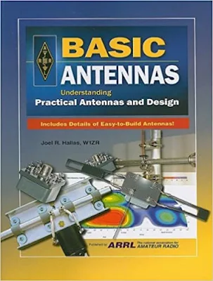
Arrl Antenna Book Review : Basic Antennas, Understanding Practical Antennas and Design

This Book written by Joel R. Hallas cover Basic Antennas Design and Practical with 26 Chapter and 2 Appendix  , suitable for college,student, and hobbyists and other enthusiasm in Antenna field.

Very good book for Professional and Amateur Enthusiasm for reference DIY Antennas , and how to design and build Do It by Yourself.

From Chapter 1, discuss about what an antenna is ? , the concept of antenna with Practical understanding and example in Practical and real life. 
Chapter 2, Half Wave Dipole Antenna in Free Space 
Chapter 3, The Field from a Dipole Near The Earth
Chapter 4, The Impedance of Antennas
Chapter 5, Transmission Lines
Chapter 6. Making Real Dipole Antennas
Chapter 7, The Field From Two Horizontal Dipoles 
Chapter 8, The Field From Two Vertical Dipoles
Chapter 9, Transmissions Lines as Transformers
Chapter 10, Practical Two Element Antenna Arrays 
Chapter 11, Wideband Dipole Antennas
Chapter 12, Multiband Dipole Antennas 
Chapter 13, Vertical Monopole Antennas
Chapter 14, Arrays of Vertical Monopole Antennas
Chapter 15 Practical Multielement Driven Arrays
Chapter 16, Surface Reflector Antennas
Chapter 17, Surface Reflector Antennas You Can Build
Chapter 18, Antenna Arrays With Parasitically Coupled Elements
Chapter 19, The Yagi-Uda or Yagi, Parasitically Coupled Antenna
Chapter 20, Practical Yagis for HF and VHF
Chapter 21,Log Periodic Dipole Arrays
Chapter 22,Loop Antennas
Chapter 23, Loop Antennas You Can Build
Chapter 24, Antennas for Microwave Applications
Chapter 25, Vehicle Antennas
Chapter 26, Antenna Measurements
Appendix A Getting Started in Antenna Modeling with EZNEC
Appendix B Using Decibels in Antenna Calculations Index

Make A Simple Halfwave Dipole Antenna for TV

In this article I will show you how to make simple a halfwave dipole antenna for home TV reception using 2 radiators , consist of two 1/4L coaxial cable and feed point .
The video for how to make this simple antenna also you can watch on my youtube channel.

Digital TV frequency band is 470-800 MHz , depends on your country and location, you can adjust with your own frequency used. So, based on that frequency , we will design the radiator Length (L) of Antennas, as in Simple A Halfwave Principle Antenna Design .


For High Frequency, we used formula :

                                                                 L = 468/Fmhz 

Center Frequency of 470-800 MHz is 635 MHz

                                                                L = 468/635
                                                                 
                                                                   = 0.737 ft

                                                                   = 0.113 meter  (approximately)
                              
                                                                   = 11.3 cm

                                                          1/2L  = 5.65 cm

So, we will make 2 radiators using coaxial cable with length 5.65 cm each

Wire Direction Antenna

A directional antenna has the ability to enhance reception of desired signals, while rejecting undesired signals arriving from slightly different directions. Although directivity normally means a beam antenna, or at least a rotatable dipole, there are certain types of antenna that allow fixed antennas to be both directive and variable.


See Chap. 7 for fixed but variable directional antennas and Chap. 11 for fixed and non-variable directive arrays. Those antennas are transmitting antennas, but they work equally well for reception. This section shows a crude, but often effective, directional antenna that allows one to select the direction of reception with pin plugs or switches.

Consider Fig. 13-10. In this case, a number of quarter-wavelength radiators are fanned out from a common feedpoint at various angles from the building. 

At the near end of each element is a female banana jack. A pair of balanced feedlines from the receiver (300-Ω twin lead, or similar) are brought to the area where the antenna elements terminate. 

Each wire in the twin lead has a banana plug attached. By selecting which banana jack is plugged into which banana plug, you can select the directional pattern of the antenna. If the receiver is equipped with a balanced antenna input, then simply connect the other end of the twin lead direction to the receiver. 

Otherwise, use one of the couplers shown in Fig. 13-11. Figure 13-11A shows a balanced antenna coupler that is tuned to the frequency of reception. 

The coil is tuned to resonance by the interaction of the inductor and the capacitor. Antenna impedance is matched by selecting the taps on the inductor to which the feedline is attached. A simple RF broadband coupler is shown in Fig. 13-11B. 

This transformer is wound over a ferrite core, and consists of 12 to 24 turns of no. 26 enameled wire, with more turns being used for lower frequencies, and fewer for higher frequencies. Experiment with the number of turns in order to determine the correct value. 

Alternatively, use a 1:1 balun transformer instead of Fig. 13-11B; the type intended for amateur radio antennas is overkill powerwise, but it will work nicely.