Find the best antennas for TV, radio, and wireless. Compare top antenna deals, use free antenna calculators, follow DIY guides, and buy high-performance antennas with confidence.
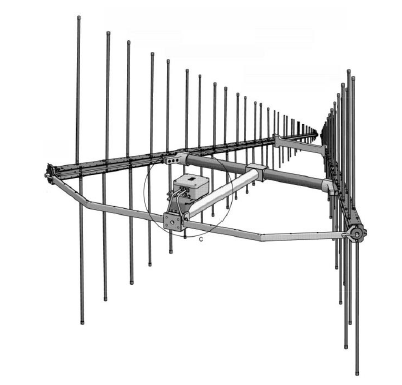
Log Periodic Antenna
Antenna Impedance Measurement
Input Impedance
 | ||
| Forward and reflected power due to mismatch The amount of reflected power can be calculated based on the equivalent circuit
diagram of a transmit antenna (see Figure below). For optimum performance, the impedance of the transmitter (ZS) must be matched to
the antenna input impedance Zin. According to the maximum power transfer theorem,
maximum power can be transferred only if the impedance of the transmitter is a
complex conjugate of the impedance of the antenna and vice versa. Thus the following
condition for matching applies: 𝑍𝑖𝑛 = 𝑍𝑆
∗
𝑤ℎ𝑒𝑟𝑒 𝑍𝑖𝑛 = 𝑅𝑖𝑛 + 𝑗𝑋𝑖𝑛 𝑎𝑛𝑑 𝑍𝑆 = 𝑅𝑆 + 𝑗𝑋𝑆 If the condition for matching is not satisfied, then some power may be reflected back
and this leads to the creation of standing waves, which are characterized by a
parameter called Voltage Standing Wave Ratio (VSWR). The VSWR is defined (as implicated by its name) as the ratio of the maximum and
minimum voltages on a transmission line. However it is also possible to calculate
VSWR from currents or power levels as the following formula shows: Another parameter closely related to the VSWR is the reflection coefficient r. It is
defined as the ratio of the amplitude of the reflected wave Vrefl to the amplitude of the
incident wave Vforw : It is furthermore related to the VSWR by the following formula: The return loss ar derives from the reflection coefficient as a logarithmic measure: So there are in fact several physical parameters for describing the quality of
impedance matching; these can simply be converted from one to the other as required.
For easy conversion please refer to the table below: Baluns and Impedance MatchingAn Antenna is normally connected to a transmission line and good matching between them is very important. A coaxial cable is often employed to connect an antenna mainly due to its good performance and low cost. A half-wavelength dipole antenna with impedance of about 73 ohms is widely used in practice. From the impedance -matching point, this dipole can match well with a 50 or 75 ohm standard coaxial cable . Now the question is : can we connect a coaxial cable directly to a dipole ? As illustrated n figure below . when a dipole is directly connected to a coaxial cable, there is a proble: A part of the current comming from the outer conductor of the cable may go to the outside of the outer conductor at the end and return to the source rather than flow to the dipole .
This undesirable current will make the cable become part of the antenna and radiate or receive unwated signal, which could be a very serious problem in some cases. In order to resolve this problem, a balun is required. The term balun is an abbreviation of the two words balance and unbalance. It is a device that connects a balanced antenna ( a dipole , in this case) to an unbalanced transmission line (a coaxial cable, where the inner conductor is not balanced with the outer conductor). The aim is to eliminate the undesirable current comming back on the outside of the cable. There are a few baluns developed for this important application. Figure below shows two examples . The sleeve balun is a very compact configuration: a metal tube of 1/4 Lambda is added to cable to form another transmission line (a coax again) with the outer conductor cable , and a short circuit is made at the base which produces an infinite impedance at the open top. The Leaky current is reflected back with a phase shift of 180 degrees, which results in the cancellation of the unwanted current on the outside of the cable. This balun is a narrowband device. If the short-circuit end is made as a sliding bar, it can be adjusted for a wide frequency range (but it is still a narrowband device). The second example is a ferrite-bead choke placed on the outside of the coaxial cable. It is widely used in EMC Industry and its function is to produce a high impedance, more precisely high inductance due to the large bandwidth may be obtained ( an octave or more). But this device is normally just suitable for frequencies below 1 GHz. which is determined by the ferrite properties it can be lossy, which can reduce the measured antenna efficiency. |
Build This Simple Logic Probe Memory Circuit
Logic Probe Memory Circuit - The Circuit describe is a low cost logic probe with memory with IC TTL 74107 Dual JK Flip Flop , Diode, resistor, and normaly closed switch provides the probe with memory function that really comes ih handy for "trapping" very fast pulse indications. See the circuit diagram. IC1 used TTL 7404. Used 5V adaptor/or battery.
Office 365 Backup Solutions
With the right data protection strategy, of course, businesses can protect data in Microsoft 365 from the threat of loss. That's why a solution is still needed even if you believe your business data is safe in Microsoft 365. One of them is using a cloud backup solution.
In this article we will lists about Best office 365 backup solutions
Office 365 Backup Solutions Software
ACRONIS CYBER PROTECT CLOUD INCLUDES:
ADVANCED BACKUP ADDS :
Storagecraft
- An employee deleting a file by mistake and then closing the application.
- A disgruntled employee purposely destroying information that is useful to the company
- Someone gaining unauthorized access to company data and deleting files
Datto
VeeAM
eset
- Secure Your Office 365 data from any cybersecurity threat with Sophos Intercept X Advanced technology
- Back up all or select OneDrive accounts
- Quickly recover files, folders or entire accounts
- Store backups on-premises and in cloud storage
- Reduce storage capacity with hyper-efficient global deduplication
- Copy backups to tape devices, tape libraries, and cloud locations, including the Arcserve Cloud, Amazon S3 and Azure Blob Storage
And, while some businesses rely on native Microsoft Office 365 backup tools, doing so puts you at risk of data loss from human error, intentional deletion, external security threats, and programmatic issues.
Gain control and work worry-free with comprehensive protection for Exchange Online, SharePoint Online and OneDrive for Business as well as other physical, virtual and cloud workloads.
Antenna Grounding Kit
Outdoor Antenna Installation Tips
Looking for more guidance or want to educate yourself before cutting the cord? Here are some tips tailored to safely installing your outdoor TV antenna.
Please note: Every time you move or reconnect your antenna, you must scan for channels on your television. Consult your television owner's manual for more precise guidelines. We include Quick Start guides with all our TV antennas and also provide them here on our website for free.
Installation tips:
- Before installing an antenna permanently on a roof or in your attic, test reception in that area and other locations prior to installation. To perform a test, connect the coaxial cable from the antenna to your TV. Then, place your antenna in the desired location. Turn on your TV using your TV and, using your remote, complete a channel scan. Once complete, flip through your TV channels and watch for signal interruptions. Make sure your antenna is installed where you get the best signal and the highest number of available channels.
- Higher is always better. Mount the antenna on your roof or in the attic for optimal performance. These locations are more likely to experience fewer obstacles which cause signal interference between the antenna and broadcast towers.

- Face the front of the antenna toward the broadcast towers. Even multi-directional antennas require this to achieve the best possible reception. Don't know where your towers are? Visit our transmitter locator or download our free Antenna Point app.
- Check your outdoor antenna regularly for secure coaxial cable connections and signs of corrosion. Sometimes debris or humidity can interfere with reception. Where possible, cover all connections and use waterproof sealant when installing an antenna mast. (See our included sealing pads for reference.)
- Installing your antenna near power lines is dangerous. The antenna must be at least 20 ft. (6 meters) away from all power lines. If any part of the antenna or mast assembly comes into contact with a power line, call your local power company. Do not remove it yourself.
Note: Unfortunately, sometimes antennas are returned to us in perfect working order but were returned due to faulty installation techniques. Continue reading for troubleshooting tips.
Troubleshooting tips:
Spotty reception with accessories:
- For the best reception, make sure the coaxial cable is the correct length for your installation needs. Similar to getting your antenna up high, terminating your coaxial cable at the right length will provide better reception to your television.
- If you are using a splitter, diplexer, or your cable run must be longer than 100 ft., consider using a preamplifier to boost weak signals.
Spotty reception:
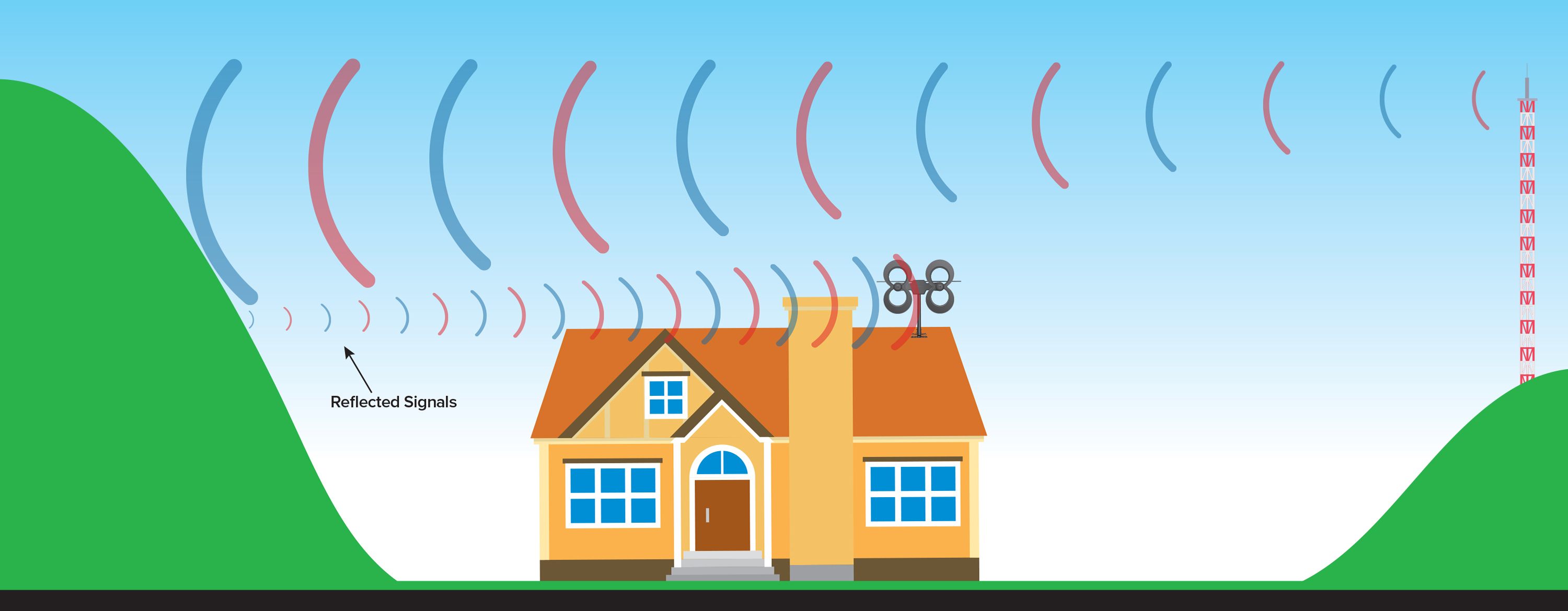
- Reflected signals are also called "multipath interference". For those living close to broadcast towers, signal loss can occur when strong signals bounce off nearby buildings and other surfaces in the area. Aim your antenna in different directions, even sometimes away from the towers, and scan for channels. If this doesn't improve your reception, your installation may require an attenuator.

- Do not install your antenna near metallic objects or reflective surfaces, as this could also cause signal interference.
- Since the switch in 2007 from analog to digital signals, receiving TV signal is "all or nothing". You won't see "fuzz" or "snow" on your TV screen if the signal is weak or there is no signal. When a digital signal is received, it will display crystal-clear on your TV. If the signal is interrupted, your TV screen will be blank.
Combining multiple antennas
When combining multiple antennas on the same mast, keep at least 4 to 6 feet of vertical separation between the two antennas to prevent interference. If you want to combine signals from a UHF antenna with a VHF antenna so there is only one down-lead going into your house, use our UHF/VHF signal combiner with a channel filter for each antenna, designed not to pick up out-of-phase signals through the other antenna. For the best results, use equal lengths of coaxial cable from the output of each antenna when connecting to the UHF/VHF combiner.
Optional grounding information
For outdoor TV antenna installations, grounding the coaxial cable will protect your equipment from voltage surges created by nearby lightning strikes but will not protect from a direct strike. Check your local electrical codes to make sure your installation is in compliance. We recommend calling a professional electrician to advise or install your antenna. We have an educational page with suggestions for grounding your antenna.
Safety precautions:
If you are installing an antenna on the roof, assemble the antenna on the ground. Installing an antenna on windy days can be especially dangerous and even slight winds create strong resistance when attempting to set up an antenna or mast.
Antennas that are improperly installed or mounted on inadequate structures are very susceptible to wind and weather damage. This damage could become life-threatening. The owner and installer assume full responsibility for the installation and verification that it is structurally sound to support all loads (weight, wind, ice, etc.) and is properly sealed against the elements and leaks.
Antennas Direct®, Inc. is not responsible or liable for any damage or injury resulting from antenna installations or by an antenna system failure due to any unknown variable applications.


,%20H-plane%20(blue).PNG)


