Antenna Handbook

Dual Band J Pole Antenna

  Dual band J-pole antenna:

A dual band J-pole antenna is a type of antenna that can be used to transmit and receive radio waves on two different frequencies. It is made up of two parallel wires that are fed at a point that is one-quarter wavelength from each end. The length of the wires is determined by the frequencies that the antenna is designed to operate in.

The two wires in a dual band J-pole antenna are typically spaced apart by a quarter wavelength. This helps to ensure that the antenna is resonant and that it radiates efficiently on both frequencies.

Dual band J-pole antennas are typically used for amateur radio applications, but they can also be used for other applications, such as public safety communications and wireless networking. They are a good choice for these applications because they are relatively easy to build and install, and they offer good performance.

Here are some of the key features of a dual band J-pole antenna:

  • It can be used to transmit and receive radio waves on two different frequencies.
  • It is relatively easy to build and install.
  • It offers good performance on both frequencies.
  • It is a versatile antenna that can be used for a variety of applications.

Here are some of the applications of a dual band J-pole antenna:

  • Amateur radio
  • Public safety communications
  • Wireless networking
  • CB radio
  • Ham radio
  • Two-way radio


To design a dual band J-pole antenna, you will need to know the frequencies that you want the antenna to operate in. The formula for calculating the length of the wires is:

length = wavelength / 2

where:

  • length is the length of the wire in meters
  • wavelength is the wavelength of the radio waves in meters

For example, the wavelength of radio waves at 145 MHz is 1.995 meters. So, for a dual band J-pole antenna that is designed to operate on 145 MHz and 440 MHz, the length of the wires would be 0.9975 meters and 0.49875 meters, respectively.

Once you know the length of the wires, you can start designing the antenna. The two wires can be made of any type of metal, but copper is a good choice. The wires should be mounted on a mast or tower that is at least as tall as the length of the wires.

The two wires should be spaced apart by a quarter wavelength. This helps to ensure that the antenna is resonant and that it radiates efficiently on both frequencies.

The dual band J-pole antenna can be fed with either a balanced or unbalanced signal. A balanced signal is required for the best performance, but an unbalanced signal can also be used.

If you are considering designing a dual band J-pole antenna, I recommend that you consult with an antenna engineer to ensure that you choose the right antenna for your needs.

Here are some additional details about the design of dual band J-pole antennas:

  • The length of the wires can be adjusted to tune the antenna to the desired frequencies.
  • The two wires can be made of different materials to improve the performance of the antenna.
  • The two wires can be bent or folded to improve the radiation pattern of the antenna.

The design of a dual band J-pole antenna can be complex, and there are many factors to consider. If you are not familiar with antenna design, I recommend that you consult with an antenna engineer.

V Antenna

 Here is an image of a V antenna:

A V antenna is a type of dipole antenna that is made up of two long wires that are arranged in a V-shape. The two wires are fed with a balun, which is a device that converts between a balanced and unbalanced signal.

V antennas are typically used for medium to high frequency applications, such as amateur radio, FM broadcasting, and public safety communications. They are a good choice for these applications because they are relatively easy to build and install, and they offer good performance.

The length of the wires in a V antenna is determined by the frequency it is designed to operate in. The formula for calculating the length of the wires is:

length = wavelength / 2

where:

  • length is the length of the wire in meters
  • wavelength is the wavelength of the radio waves in meters

For example, the wavelength of radio waves at 145 MHz is 1.995 meters. So, for a V antenna with a frequency of 145 MHz, the length of the wires would be 0.9975 meters.

The height of the V antenna can also affect its performance. A higher antenna will have a better radiation pattern, but it will also be more susceptible to interference from objects on the ground.

V antennas are a versatile and effective type of antenna that can be used for a variety of applications. They are relatively easy to build and install, and they offer good performance.


V Antenna Design Calculator

V antenna design calculator:

Frequency (MHz): 145
Height (m): 10

Element length (m): 5.263157894736842

This calculator calculates the length of the elements of a V antenna for a given frequency and height. The formula used is:

length = wavelength / 2

where:

  • length is the length of the element in meters
  • wavelength is the wavelength of the radio waves in meters

The wavelength of the radio waves can be calculated using the formula:

wavelength = c / frequency

where:

  • c is the speed of light in meters per second
  • frequency is the frequency of the radio waves in hertz

For example, the wavelength of radio waves at 145 MHz is:

wavelength = c / frequency = 299,792,458 m/s / 145 MHz = 1.995 m

So, for a V antenna with a frequency of 145 MHz and a height of 10 meters, the length of the elements would be:

  • Element length = 0.9975 m

This calculator is just a simple example, and there are many other factors that can affect the length of the elements of a V antenna. For more accurate results, you should consult a qualified antenna engineer.

Here are some of the factors that can affect the length of the elements of a V antenna:

  • The dielectric constant of the material the antenna is made of
  • The thickness of the antenna
  • The conductivity of the material the antenna is made of
  • The ground conductivity

If you are designing a V antenna for a specific application, it is important to consider all of these factors to ensure that the antenna will perform as expected.


Super J Antenna Calculator

 Here is a Super J antenna calculator:

Frequency (MHz): 145
Feed point height (m): 1

Element 1 length (m): 0.7071067811865475
Element 2 length (m): 0.3535533905932737

This calculator calculates the length of the elements of a Super J antenna for a given frequency and feed point height. The formula used is:

length = wavelength / 2 - feed_point_height

where:

  • length is the length of the element in meters
  • wavelength is the wavelength of the radio waves in meters
  • feed_point_height is the height of the feed point of the antenna in meters

The wavelength of the radio waves can be calculated using the formula:

wavelength = c / frequency

where:

  • c is the speed of light in meters per second
  • frequency is the frequency of the radio waves in hertz

For example, the wavelength of radio waves at 145 MHz is:

wavelength = c / frequency = 299,792,458 m/s / 145 MHz = 2.046 m

So, for a Super J antenna with a frequency of 145 MHz and a feed point height of 1 meter, the lengths of the elements would be:

  • Element 1 length = 0.7071067811865475 m
  • Element 2 length = 0.3535533905932737 m

This calculator is just a simple example, and there are many other factors that can affect the length of the elements of a Super J antenna. For more accurate results, you should consult a qualified antenna engineer.

do-it-yourself j antennas for 145 MHz drawings

 Here are some do-it-yourself J antennas for 145 MHz drawings:

  • J-pole antenna: A J-pole antenna is a simple and effective antenna that can be made from a few materials. It is a good option for beginners who are looking to build their own antenna.

To make a J-pole antenna, you will need:

* A piece of wire that is 1/4 wavelength long at 145 MHz.
* A connector for your radio.
* A way to mount the antenna.

The wire can be any type of metal, but copper is a good choice. The length of the wire will depend on the frequency you are using. For 145 MHz, the wire should be about 25 inches long.

The connector can be a BNC connector, PL-259 connector, or any other connector that is compatible with your radio.

The antenna can be mounted on a mast, a wall, or any other suitable surface.

  • Terminated J-pole antenna: A terminated J-pole antenna is a variation of the J-pole antenna that has a resistor at the end of the antenna. The resistor helps to absorb the radio waves that are not transmitted or received by the antenna. This helps to prevent the antenna from radiating harmful interference.

To make a terminated J-pole antenna, you will need:

* A piece of wire that is 1/4 wavelength long at 145 MHz.
* A resistor that is rated for the power output of your radio.
* A connector for your radio.
* A way to mount the antenna.

The wire and resistor can be the same as for a standard J-pole antenna. The connector can be a BNC connector, PL-259 connector, or any other connector that is compatible with your radio.

The antenna can be mounted on a mast, a wall, or any other suitable surface.

  • Folded J-pole antenna: A folded J-pole antenna is a variation of the J-pole antenna that has a second piece of wire that is folded in half. The folded wire helps to improve the radiation pattern of the antenna.

To make a folded J-pole antenna, you will need:

* Two pieces of wire that are 1/4 wavelength long at 145 MHz.
* A connector for your radio.
* A way to mount the antenna.

The wires can be the same as for a standard J-pole antenna. The connector can be a BNC connector, PL-259 connector, or any other connector that is compatible with your radio.

The antenna can be mounted on a mast, a wall, or any other suitable surface.

These are just a few examples of do-it-yourself J antennas for 145 MHz. There are many other designs available, and you can experiment to find the one that works best for you.

It is important to note that building your own antenna can be a challenging project. If you are not comfortable working with electrical equipment, you should consult with a qualified amateur radio operator.

LW Antenna Design

A longwave (LW) antenna is an antenna that is designed to transmit or receive radio waves in the longwave band, which ranges from 150 to 525 kilohertz (kHz). LW antennas are typically large and cumbersome, as the wavelength of longwave radio waves is very long.

Here are some of the most common types of LW antennas:

  • Vertical antenna: A vertical antenna is the simplest type of LW antenna. It consists of a single vertical conductor, such as a metal rod or pipe. The length of the antenna should be one-quarter of the wavelength of the radio waves it is designed to transmit or receive.
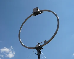
  • Loop antenna: A loop antenna is a circular or elliptical antenna. It is made up of a single conductor that is bent into a circle or ellipse. The diameter of the loop should be one-half of the wavelength of the radio waves it is designed to transmit or receive.
  • Ground-plane antenna: A ground-plane antenna is a vertical antenna that is surrounded by a ground plane. The ground plane is a conducting surface, such as a metal sheet or a network of wires, that is placed below the antenna. The ground plane helps to improve the radiation pattern of the antenna.
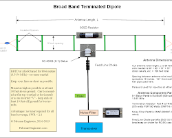
  • Terminated antenna: A terminated antenna is an antenna that is terminated in a resistor. The resistor absorbs the radio waves that are not transmitted or received by the antenna. This helps to prevent the antenna from radiating harmful interference.

The design of an LW antenna depends on a number of factors, including the frequency band it is designed to operate in, the desired radiation pattern, and the amount of space available.

If you are planning to build an LW antenna, it is important to consult with a qualified antenna engineer to ensure that the antenna is designed correctly.

Here are some of the things to consider when designing an LW antenna:

  • Frequency band: The frequency band that the antenna is designed to operate in will determine the length of the antenna.
  • Radiation pattern: The radiation pattern of an antenna describes how the radio waves are emitted from the antenna. There are many different radiation patterns that can be used for LW antennas.
  • Space available: The amount of space available will determine the size and shape of the antenna.
  • Cost: The cost of the antenna will depend on the materials used and the complexity of the design.

Once you have considered these factors, you can start designing your LW antenna. There are many resources available to help you design an antenna, such as books, websites, and software programs.