
We sell TWINAX RF Connector


We sell Connector UHF Series

UHF Hood Panel Mount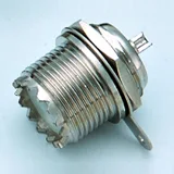 UHF Jack Chassis Mount
 UHF Jack Panel Mount
 UHF Jack To Jack
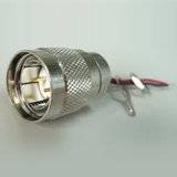
 UHF Plug Crimp
 UHF Plug Solder Type
 UHF Plug Twist On


Field Strength Meter using MOSFET BF 900
Field Strength Meter is very useful tools for HAM Radio and hobbyist for measuring Power output of Antenna transmitter, such CB Radio, 80 meter transceiver and etc.
For the RF circuit, it is need special soldering and connection between component and grounding also must in good condition, for avoiding wild capacitance.
 For Field strength meter , should be sensitive, that's why we are using RF Mosfet BF900 . The strengthening arrange by Potensio resistor P1, and SW2 switch is selector for choose stride frequency of antenna that want to calibration.
S1 : 480 kHz ... 2.4 MHz (L1)
S2 : 24 kHz...... 12 MHz (L2) , and
S3 : 12 kHz...... 40 MHz (L3)
How to soldering RF Board and Good Grounding in RF circuit :
Avoiding long wire component on soldering, the short of the leg of component more goods. Avoiding small grounding, 70% of RF board should be grounding, and if there was coil and oscillator, should be covered by aluminium or separated from other active component, so the frequency not change.
For the RF circuit, it is need special soldering and connection between component and grounding also must in good condition, for avoiding wild capacitance.

S1 : 480 kHz ... 2.4 MHz (L1)
S2 : 24 kHz...... 12 MHz (L2) , and
S3 : 12 kHz...... 40 MHz (L3)
How to soldering RF Board and Good Grounding in RF circuit :
Avoiding long wire component on soldering, the short of the leg of component more goods. Avoiding small grounding, 70% of RF board should be grounding, and if there was coil and oscillator, should be covered by aluminium or separated from other active component, so the frequency not change.
470-800 MHZ dipole antenna design using 4nec2 software tools
470-800 MHZ is television reception band frequency , so we calculate Center frequency = 635 MHZ
Enter this centre frequency to the Geometry calculation 4nec2 software :
0.472 meter is lambda/2 for 635 MHz according to software .
0.009 is radius of wire in meter , equal to 9 mm pipe radius, made from copper
then calculate the formula by clicking F7 or go to calculate menu, then click NEC output data. The result is :
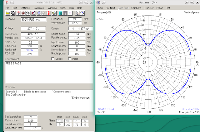 SWR still high 10.3 , we must re calculate for finding the best SWR, SWR wanted between 1.1 until 3 . And this is only sample for designing using 4NEC2 software for dipole antenna.
The Power output antenna also 3.94 dBi and the pattern antenna shows beside Main windows calculation.
This is 2D view of antenna with current propagation
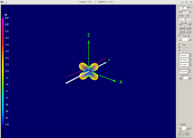
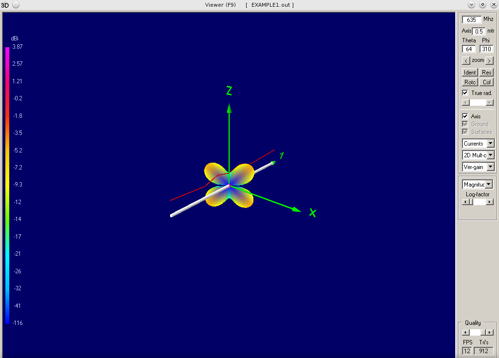
This is 3D view of antenna pattern , with x,y,z cartesian with Power maximum at 3.87 dBi

3D view of antenna Zoom in

3D view of Vertical Gain calculation antenna

Current View of Antenna with Hide Pattern in Horizontal Propagation

3D Multicolor view of antenna with current propagation

3D Horizontal Gain with Current propagation in Horizontal view

2D Slices with horizontal current

Vertical gain antenna with current pattern

Vertical gain antenna with current propagation,

Enter this centre frequency to the Geometry calculation 4nec2 software :

0.472 meter is lambda/2 for 635 MHz according to software .
0.009 is radius of wire in meter , equal to 9 mm pipe radius, made from copper
then calculate the formula by clicking F7 or go to calculate menu, then click NEC output data. The result is :

The Power output antenna also 3.94 dBi and the pattern antenna shows beside Main windows calculation.
This is 2D view of antenna with current propagation
This is 3D view of antenna pattern , with x,y,z cartesian with Power maximum at 3.87 dBi

3D view of antenna Zoom in

3D view of Vertical Gain calculation antenna
Current View of Antenna with Hide Pattern in Horizontal Propagation

3D Multicolor view of antenna with current propagation

3D Horizontal Gain with Current propagation in Horizontal view

2D Slices with horizontal current

Vertical gain antenna with current pattern

Vertical gain antenna with current propagation,

Subscribe to:
Posts (Atom)