transmissionlines must be analyzed in terms of an RLC network.
Parallel and coaxial lines
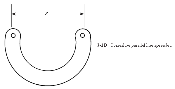
This article will consider several types of transmission lines. Both step-functionand sine-wave ac responses will be studied. Because the subject is both conceptualand analytical, both analogy and mathematical approaches to the theory of trans-mission lines will be used.Figure 3-1 shows several basic types of transmission line. Perhaps the oldest andsimplest form is the parallel lineshown in Figs. 3-1A through 3-1D. Figure 3-1A shows an end view of the parallel conductor transmission line. The two conductors,of diameter d, are separated by a dielectric (which might be air) by a spacing S.These designations will be used in calculations later. Figure 3-1B shows a type ofparallel line called twin lead. This is the old-fashioned television antenna transmis-sion line. It consists of a pair of parallel conductors separated by a plastic dielectric.TV-type twin lead has a characteristic impedance of 300 Ω, while certain radio trans-mitting-antenna twin lead has an impedance of 450 Ω. Another form of twin lead isopen line, shown in Fig. 3-1C. In this case, the wire conductors are separated by anair dielectric, with support provided by stiff (usually ceramic) insulators. A tie wire(only one shown) is used to fasten each insulator end to the main conductor. Someusers of open line prefer the form of insulator or supporter shown in Fig. 3-1D.
This form of insulator is made of either plastic or ceramic, and is in the form of a U. Thepurpose of this shape is to reduce losses, especially in rainy weather, by increasingthe leakage currents path relative to spacing S.Parallel lines have been used at VLF, MW, and HF frequencies for decades. Evenantennas into the low VHF are often found using parallel lines. The higher imped-ance of these lines (relative to coaxial cable) yields lower loss in high-power appli-cations. For years, the VHF, UHF, and microwave application of parallel lines waslimited to educational laboratories, where they are well suited to performing exper-iments (to about 2 GHz) with simple, low-cost instruments. Today, however, printedcircuit and hybrid semiconductor packaging has given parallel lines a new lease onlife, if not an overwhelming market presence.Figure 3-1E shows a form of parallel line called shielded twin lead. This type of lineuses the same form of construction as TV-type twin lead, but it also has a braided shield-ing surrounding it. This feature makes it less susceptible to noise and other problems.The second form of transmission line, which finds considerable application atmicrowave frequencies, is coaxial cable(Figs. 3-1F through 3-1L). This form ofline consists of two cylindrical conductors sharing the same axis (hence “coaxial”),and separated by a dielectric (Fig. 3-1F). For low frequencies (in flexible cables)the dielectric may be polyethylene or polyethylene foam, but at higher frequenciesTeflonand other materials are used. Also used, in some applications, are dry air anddry nitrogen.
Several forms of coaxial line are available. Flexible coaxial cable is perhaps themost common form. The outer conductor in such cable is made of either braid or foil(Fig. 3-1G). Television broadcast receiver antennas provide an example of such cablefrom common experience. Another form of flexible or semiflexible coaxial line is heli-cal line(Fig. 3-1H) in which the outer conductor is spiral wound.Hardline(Fig.3-1I) is coaxial cable that uses a thin-wall pipe as the outer conductor. Some hardlinecoax used at microwave frequencies has a rigid outer conductor and a solid dielectric.Gas-filled lineis a special case of hardline that is hollow (Fig. 3-1J), the centerconductor is supported by a series of thin ceramic or Teflon insulators. The dielec-tric is either anhydrous (i.e., dry) nitrogen or some other inert gas.Some flexible microwave coaxial cable uses a solid “air-articulated” dielectric(Fig. 3-1K), in which the inner insulator is not continuous around the center con-ductor, but rather is ridged. Reduced dielectric losses increase the usefulness of the
cable at higher frequencies. Double-shielded coaxial cable (Fig. 3-1L) provides anextra measure of protection against radiation from the line, and EMI from outsidesources, from getting into the system.Stripline, also called microstripline(Fig. 3-1M), is a form of transmission lineused at high UHF and microwave frequencies. The stripline consists of a criticallysized conductor over a ground-plane conductor, and separated from it by a dielec-tric. Some striplines are sandwiched between two groundplanes and are separatedfrom each by a dielectric.
(from Practical Antenna Handbook by Joseph J Carr)


No comments:
Post a Comment