The tilted, center-fed, terminated, folded dipole(TCFTFD, also called the T2FD or TTFD) is an answer to both the noise pickup and length problems that sometimes affect other antennas. For example, a random-length wire, even with antenna tuner, will pick up considerable amounts of noise. A dipole for 40 m is 66 ft long.
This antenna was first described publicly in 1949 by Navy Captain C. L. Countryman, although the U.S. Navy tested it for a long period in California during World War II. The TCFTFD can offer claimed gains of 4 to 6 dB over a dipole, depending on the frequency and design, although 1 to 3 dB is probably closer to the mark in practice, and less than 1 dB will be obtained at some frequencies within its range (especially where the resistor has to absorb a substantial portion of the RF power). The main attraction of the TCFTFD is not its gain, but rather its broad bandedness.
In addition, the TCFTFD can also be used at higher frequencies than its design frequency. Some sources claim that the TCFTFD can be used over a 5 or 6:1 frequency range, although my own observations are that 4:1 is more likely. Nonetheless, a 40-m antenna will work over a range of 7000 to 25,000 kHz, with at least some decent performance up into the 11-m Citizen’s Band (27,000 kHz).
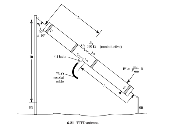
The basic TCFTFD (Fig. 6-21) resembles a folded dipole in that it has two parallel conductors of length L, spaced a distance W apart, and shorted together at the
ends. The feedpoint is the middle of one conductor, where a 4:1 balun coil and 75-Ω coaxial-cable transmission line to the transceiver are used. A noninductive, 390-Ω resistor is placed in the center of the other conductor. This resistor can be a carbon-composition (or metal-film) resistor, but it must not be a wirewound resistor or any other form that has appreciable inductance. The resistor must be able to dissipate about one-third of the applied RF power. The TCFTFD can be built from ordinary no.14 stranded antenna wire.
For a TCFTFD antenna covering 40 through 11 m, the spread between the conductors should be 191⁄2 in, while the length L is 27 ft. Note that length L includes one-half of the 19-in spread because it is measured from the center of the antenna element to the center of the end supports.
The TCFTFD is a sloping antenna, with the lower support being about 6 ft off the ground. The height of the upper support depends on the overall length of the antenna. For a 40-m design, the height is on the order of 50 ft.
The parallel wires are kept apart by spreaders. At least one commercial TCFTFD antenna uses PVC spreaders, while others use ceramic. You can use wooden dowels of between 1-in and 5⁄8-in diameter; of course, a coating of varnish (or urethane spray) is recommended for weather protection. Drill two holes, of a size sufficient to pass the wire, that are the dimension W apart (19 in for 40 m). Once the spreaders are in place, take about a foot of spare antenna wire and make jumpers to hold the dowels in place. The jumper is wrapped around the antenna wire on either side of the dowel, and then soldered.
The two end supports can be made of 1 × 2 in wood treated with varnish or urethane spray. The wire is passed through screw eyes fastened to the supports. A support rope is passed through two holes on either end of the 1 × 2 and then tied off at an end insulator.
The TCFTFD antenna is noticeably quieter than the random-length wire antenna, and somewhat quieter than the half-wavelength dipole. When the tilt angle is around 30°, the pattern is close to omnidirectional. Although a little harder to build than dipoles, it offers some advantages that ought not to be overlooked. These dimensions will suffice when the “bottom end” frequency is the 40-m band, and it will work well on higher bands.
From The Book " Practical Antenna Handbook " Joseph P. Carr

No comments:
Post a Comment