ought to produce the pattern of Fig. 11-1B—yet experience shows this claim is false. It seems that there are several problems with the system in Fig. 11-2B.
First, coax has a property called velocity factor(VF), which is the fraction of the speed of light at which signals in the cable propagate. The VF is a decimal fraction on the order of 0.66 to 0.90, depending upon the type of coax used. Unfortunately, the physical spacing between A and B is a real half-wavelength (L3 = 492/F), but the cable length is shorter by the velocity factor [L3' = (VF × 492) /F].
Consider an example. A 15-m phased vertical antenna system will have two 11-ft radiators, spaced 22 ft apart (approximately, depending upon exact frequency). If we use foam coax, with VF = 0.80, the cable length is 0.8 × 22 ft, or 17.6 ft. In other words, despite lots of publicity, the cable won’t fit between the towers! Second, the patterns shown in Fig. 11-1 are dependent upon one condition: the antenna currents are equal. If both of them are the same impedance, and are fed from the same transmitter, then it is reasonable to assume that the currents are equal—right? No, wrong! What about coax loss? Because of normal coax loss, which increases at higher frequencies, the power available to antenna Bin Fig. 11-1B is less than the power available to antenna A. Thus, the pattern will be somewhat distorted, because the current produced in Bis less than the current in A, when they should be equal.
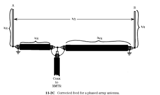
The first problem is sometimes fixed by using unequal lengths for cables L1 and L2 (Fig. 11-2A), and using it for the out-of-phase case. For example, if we make L1 one-quarter wavelength and L2 three-quarter wavelength (Fig. 11-2C), antenna A is fed with a 90° phase lag (relative to the tee connector signal), while antenna B is fed with a 270° phase shift. The result is still a 180° phase difference.
Unfortunately, we have not solved the current level problem, and may have actually made it worse by adding still more lossy cable to the system. There is still another problem that is generic to the whole class of phased verticals. Once installed, the pattern is fixed. This problem doesn’t bother most point-topoint commercial stations, or broadcasters, because they tend to transmit in only one direction. But amateurs are likely to need a rotatable pattern. Neither the antennas in Fig. 11-1A nor that in Fig. 11-1B is rotatable without a lot of effort—like changing the coax feeds, or physically digging up the verticals and repositioning them. Fortunately, there is a single solution to all three problems. Figure 11-3 shows a two-port phasing transformer made from a toroidal balun kit. Use the kind of kit that makes a 1:1 balun transformer. Although we are not making a balun, we will need enough wire to make three windings, and that is the normal case for 1:1 baluns. Amidon Associates and others make toroidal balun kits.
Wind the three coils in trifilar style, according to the kit instructions. The dots in Fig. 11-3 show the “sense” of the coils, and they are important for correct phasing; call one end the “dot end” and the other end the “plain end” to keep them separate. If the dot end of the first coil is connected to J3 (and the transmitter), then connect the dot end of the second coil to the 0° output (J1, which goes to antenna A). The third coil is connected to a DPDT RF relay or switch. In the position shown, S1 causes the antennas to be 180° out of phase. In the other position, the “sense” of the third coil is reversed, so the antennas are in phase. Another phasing method is shown in Fig. 11-4. In this scheme, two convenient, but equal, lengths of coaxial cable (L1 and L2) are used to carry RF power to the antennas. One segment (L1) is fed directly from the transmitter’s coaxial cable (L3), while the other is fed from a phasing switch. The phasing switch is used to either by
pass or insert a phase-shifting length of coaxial cable (L4). For 180° phasing use the following equation to find the length (L4):
where L is the length of L4, in feet VF is the velocity factor (a decimal fraction) FMHz is the operating frequency, in megahertz
Some people use a series of switches to select varying amounts of phasing shift from 45° to 270°. Such a switch allows them to select any number of other patterns for special situations.


No comments:
Post a Comment