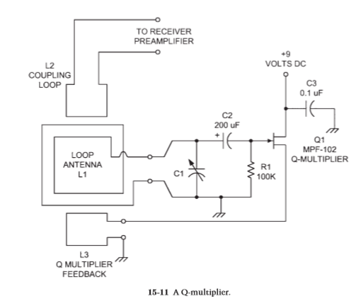
Many years ago, the Q-multiplier was a popular add-on accessory for a communications receiver. These devices were sold as Heathkits, and many construction projects could be found in magazines and amateur radio books.
The Q-multiplier has the effect of seeming to greatly increase the sensitivity of a receiver, as well as greatly reducing the bandwidth of the front end. Thus it allows better reception of some stations because of increased sensitivity and narrowed bandwidth.
A Q-multiplier is an active electronic circuit placed at the antenna input of a receiver. It is essentially an Armstrong oscillator, as shown in Fig. 15-11, that does not quite oscillate. These circuits have a tuned circuit (L1/C1) at the input of an amplifier stage and a feedback coupling loop (L3). The degree of feedback is controlled by the coupling between L1 and L3. The coupling is varied by varying both how close the two coils are and their relative orientation with respect to each other.
Certain other circuits use a series potentiometer in the L3 side that controls the amount of feedback. The Q-multiplier is adjusted to the point that the circuit is just on the verge of oscillating, but not quite. As the feedback is backed away from the threshold of oscillation, but not too far, the narrowing of bandwidth occurs, as does the increase in sensitivity. It takes some skill to operate a Q-multiplier, but it is easy to use once you get the hang of it and is a terrific accessory for any loop antenna.
Loop amplifier
Figure 15-12 shows the circuit for a practical loop amplifier that can be used with either shielded or unshielded loop antennas. It is based on junction field effect transistors (JFET) connected in cascade. The standard common-drain configuration is used for each transistor, so the signals are taken from the source terminals. The drain terminals are connected together and powered from the
12-V dc power supply.
A 2.2- F bypass capacitor is used to put the drain terminals of Q1 and Q2 at ground potential for ac signals while keeping the dc voltage from being shorted out. The two output signals are applied to the primary of a center-tapped transformer, the center tap of which is grounded.
To keep the dc on the source terminals from being shorted through the transformer winding, a pair of blocking capacitors (C4, C5) is used. The input signals are applied to the gate terminals of Q1 and Q2 through dc blocking capacitors C2 and C3. A pair of diodes (D1, D2) is used to keep high-amplitude noise transients from affecting the operation of the amplifier. These diodes are connected back to back in order to snub out both polarities of signal.
Tuning capacitor C1 is used in lieu of the capacitor in the loop and is used to resonate the loop to a specific frequency. Its value can be found from the equation given earlier. The transistors used for the push-pull amplifier (Q1, Q2) can be nearly any general-purpose JFET device (MPF-102, MPF-104, etc.). A practical approach for many people is to use transistors from service replacement lines, such as the NTE-312 and NTE-316 devices.


No comments:
Post a Comment