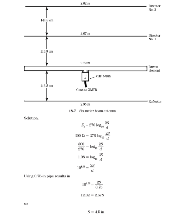
The basic Yagi was covered in Chap. 12, so we will only show examples of practical VHF devices. A 6-m Yagi antenna is shown in Fig. 18-7. This particular antenna is a four-element model. The reflector and directors can be mounted directly to a metallic boom, because they are merely parasitic.
The driven element, however, must be insulated from the metal boom. The driven element shown in Fig. 18-7 is a folded dipole. While this is common practice at VHF, because it tends to broadband the antenna, it is not strictly necessary.
The driven element, however, must be insulated from the metal boom. The driven element shown in Fig. 18-7 is a folded dipole. While this is common practice at VHF, because it tends to broadband the antenna, it is not strictly necessary.
The dimensions of the driven element are found from Eq. 18.4. Set the equation equal to 300 Ω, select the diameter of the tubing from commercially available sources, and then calculate the spacing.
Example 18-2 Calculate the spacing of a 300-Ω folded dipole when 3⁄4-in tubing is used in its construction.
This Article is from Practical Antenna Handbook by Joseph J. Carr
Example 18-2 Calculate the spacing of a 300-Ω folded dipole when 3⁄4-in tubing is used in its construction.
This Article is from Practical Antenna Handbook by Joseph J. Carr

No comments:
Post a Comment