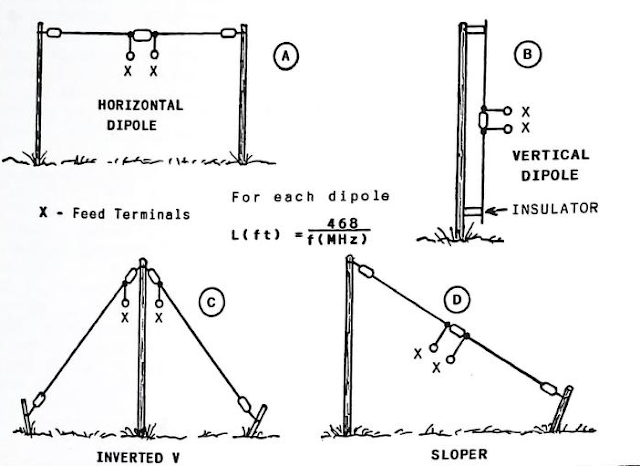
Perhaps the most common amateur antenna in use today is the dipole. It is inexpensive to construct, and it provides good results for local and DX communications if it is erected high above ground.
A dipole antenna is a 1/2-wavelength conductor that is fed at the electrical center. Gain types of directional antennas, such as the log periodic dipole array consists of a group of dipoles. In other words we can combine a number of dipoles to form a wideband log-periodic beam antenna.
A single dipole antenna has no gain, but it does exhibit a bidirectional radiation pattern if it is a half wavelength or greater above ground, and if it is erected for horizontal polarization (parallel to the earth). The radiation pattern for this type of dipole resembles a figure below. Maximum radiation is off the broad side of the antenna.
We learned that a dipole antenna loses its direct-ional characteristics when it is placed close to ground (less than approximately 0.5 wavelength). The resultant radiation pattern for a dipole that is, say, 1/20 wavelength above ground (e.g., 53 feet for 3.7 MHz), is pretty much circular. In other words, the signal is radiated almost equally in all directions. Also, the radiation angle will be very high, which is not ideal for long-distance communications.
Dipoles may be erected horizontally or vertically. They may also be configured as inverted Vs. This is a popular format because only one tall support pole or tower is needed. The center of the dipole is held aloft by the tall supporting structure, and the halves of the dipole droop toward ground at approximately 45 degrees. You may also use your dipole as a sloper (sloping dipole). In this example , see figure 1, we tie one end of the dipole to a tall mast or tower and slope the entire antenna toward ground at approximately 45 degrees. The lower end of the antenna (as with an inverted V) is just a few feet above ground-in a typical case where the tower or mast height is 50-60 feet.
Radiation angles and patterns vary in accordance with the manner in which we erect our dipole antennas. A vertical dipole, for example, has an omnidirectional radiation pattern, and it exhibits a relatively low radiation angle. Sloping dipoles and inverted Vs with an enclosed angle of 90 to 100 degrees will also radiate a vertically polarized signal. The sloper will have a unidirectional pattern off the slope of the antenna (directivity rather than gain) if it is supported by a metal Mast or tower:
the metal support device acts somewhat as a reflector, If the sloper is supported on a wooden pole, the radiation pattern will be omnidirectional.
Inverted-V antennas also have an omnidirectional pattern if they are erected in a symmetrical manner, respective to the tower and placement of the antenna legs.


No comments:
Post a Comment