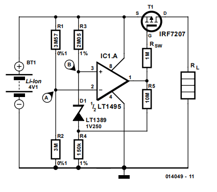
When a lithium-ion battery is discharged below the minimum recommended cell voltage its life expectancy is dramatically reduced. The circuit described here can avoid this by disconnecting the load from the battery when the cell voltage reaches a set level.The voltage at junction A may be set to 3 V, for example, by selecting the correct ratio of R1 and R2. When the battery voltage drops below the minimum value, the voltage at junction A will be smaller than that at junction B. The latter voltage is equal to:
VB = 1.25 V + I R4 = 1.37 V
where:
I = (Vmin. – 1.25 V) / (R3 + R4) = 800 nA
(Vmin. = minimum value)
At this point the output of opamp LT1495 will go high, causing SW1 (a P-channel logic level MOSFET) to block and break the connection between the battery and the load. Because the battery voltage will rise when the load is disconnected, a certain amount of hysteresis is created by the addition of R5. This prevents the circuit from oscillating around the switching point. The value of R5 shown here provides 92 mV of hysteresis. So the battery voltage has to
rise to 3.092 V before the load is reconnected to the battery. An increase or decrease of the hysteresis is possible by reducing or increasing the value of R5, respectively. The required hysteresis depends in the internal impedance of the battery and the magnitude of the load current. The switching point defined by the values of R1-R2 is
quite critical with a circuit such as this. If the switching point is too high, then the available capacity of the battery is not fully utilised. Conversely, if the switching point is too low, the battery will be discharged too far with all the harmful consequences that may entail. Using the values shown here and including the tolerances of the parts, the switching point is between 2.988 V and 3.012 V. In practice it may be easier to select slightly lower values for R1 or R2 and connect a multi-turn trimpot in series with it. This makes an accurate adjustment of the switching point possible and has the additional advantage that R1 and R2 may be ordinary 1%-tolerance types.
Finally, before using the protection circuit it is advisable to first connect it to a power supply instead of a battery and carefully verify the operation of all its features!
No comments:
Post a Comment