This articles is from Book of Digital computer electronics : an introduction to microcomputers , book written by Albert Paul Malvino.
The SAP (Simple-As-Possible) computer has been designed for the beginner. The Main Purpose of SAP is to introduce all the crucial ideas behind computer operation without burying you in unnecessary detail. But even a simple computer like SAP covers many advanced concepts. to avoid bombarding you with too much all at once, we will examine three different generations of the SAP computer.
SAP-1 is the first stage in the evolution toward modern computers. Although primitive, SAP-1 is a big step for a beginner. So, dig into SAP-1, master SAP-1, its architecture, its programming , and its circuits, Then you will be ready for SAP-2.
The Architecture
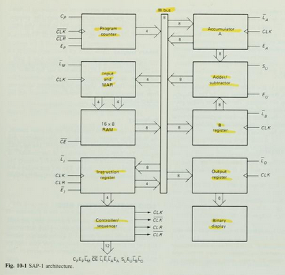
Figure 10-1 shows the (structure) of SAP-1, a bus-organized computer. All register outputs to the W bus are three-state; this allows orderly transfer of data . All other register outputs are two-state; these outputs continuously drive the boxes they are connected to.
The layout of fig. 10-1 emphasizes the registers used in SAP-1. For this reason , no attempt has been made to keep all control circuits in one block called the control unit, all input-output circuits in another block called the I/O unit, etc.
many of registersof Fig. 10-1 are already familiar from earlier examples and discussions. What follows is a brief description of each box; detailed explanations come later.
The Circuit Diagram
Program Counter
The program is stored at the beginning of the memory with the first instruction at binary address 0000, the second instruction at address 0001, the third at address 0010, and so on. The program counter, which is part of the control unit, counts from 0000 to 1111. It is job is to send to the memory the address of the next instruction to be fetched and executed. It does this as follows.
The Program Counter is reset to 0000 before each computer run. When the computer run begins, the program counter sends address 0000 to the memory. The program counter is then incremented to get 0001. After the first instruction is fetched and executed, the program counter sends address 0001 to the memory. Again the program counter is incremented. After the second instruction is fetched and executed, the program counter sends address 0010 to the memory. In this way, the program counter is keeping track of the next instruction to be fetched and executed.
The program counter is like someone pointing a finger at a list of instructions, saying do this first, do this second, do this third, etc. This is why the program counter is sometimes callled a pointer; it points to an address in memory where something important is being stored.
Input and MAR
Below the program counter is the input and MAR block. It includes the address and data switch registers. These Switch registers, which part of the input unit, allow you to send 4 address bits and 8 data bits to the RAM. As you recall, instruction and data words are written into the RAM before a computer run.
The Memory address register (MAR) is part of the SAP-1 memory. During a computer run, the address in the program counter is latched into the MAR. A bit later, the MAR applies this 4-bit address to the RAM, where a read operation is performed.
The RAM
The RAM is a 16 X 8 static TTL RAM. You can program the RAM by means of the address and data switch registers. This allows you to store a program and data in the memory before a computer run.
During a computer run, the RAM receives 4-bit addresses from MAR (Memory Address Register) and a read operation is performed, In this way , the instruction or data word stored in the RAM is placed on the W bus for use in some other part of the computer.
On the next article, I will describe Instruction register, controller sequencer, Accumulator/A Register, Adder/Subtractor, B Register, Output Register, and Binary Display.


No comments:
Post a Comment