Showing posts with label circuit. Show all posts
Showing posts with label circuit. Show all posts
HFE Transistor NPN and PNP Instrument
DIY Multifunction Led Name For Store, Wall, Open/Close Door, etc
On this Project , we will discuss about Led Name , for 8 Alphabet or more. Using IC 74LS164 TTL , 8 bit parallel out serial shift register. And Using IC 555 timer. Also transistor 9013 or BC 107.
The circuit as below :

Led Configuration using Transistor BC 107 / 9013 :

Guidance for make one alphabet .
For making 1 alphabet , we using several LED parallel / Series with one transistor . We using power supply 15 Vdc , so maximum LED series is Six, in one line. For example for 18 LED for 1 alphabet, we use this configuration :

Power Supply 5 V using IC 7805.
We can Supply SAW Resonator
We also supply the needs of SAW filters and SAW Resonator devices.
 For SAW resonator , there is one port series with a wide range of packaging and frequency of different - different. No one series port for wireless remote controller with a frequency of 105 MHz - 325 MHz.
One-port SAW resonator series with a center frequency or center frequency 105.5 MHz, insertion loss 2.5 dB, Package SF-712, tolerance +/- 75 Khz.
Here is a one port SAW resonator that we have and we can supply for the needs of factory production.
Center Frequency: 158.15 MHZ, tolerance +/- 100 KHz, insertion loss is 1.5 dB, package SF-712, center frequency: 222.15 MHz, insertion loss is 1.5 dB, tolerance +/- 100 KHz and SF-712 package.
Center Frequency of SAW Resonator available to us:
105.5 MHz, 158.15 MHz, 222.15 MHz, 300 MHz, 302 MHz, 303,325 MHz, 303,825 MHz, 303,875 MHz, 304.25 MHz, 304.3 MHz, 308.5 MHz, 310 MHz, 311 062 MHz, 313.25 MHz, 314 MHz, 314.5 MHz, 315 MHz , 315.5 MHz, 315.5 MHz, 316.8 MHz, 318 MHz, 319 508 MHz, 319.5 MHz, 324 MHz, 325 MHz.
The frequency of the SAW resonator tolerance between +/- +/- 75 KHz and 100 KHz.
No insertion loss of 2.5 dB, 1.5 dB and 1.3 dB and the type of package for a SAW resonator that is SF-712, TO-39 / 39L, SM558, SM534, F-11 / 11L, F-11L
For more details of data can be downloaded here
There is also a one-port SAW resonators in series with a frequency range of 327-868 MHz. SAW Resonator is also used for wireless remote controller.
Center
Frequency for the 327-868 MHz SAW Resonator start: 327.3 MHz, 300 MHz,
308 MHz, 340 MHz, 345 MHz, 350 MHz, 360 MHz, 372 MHz, 388.95 MHz, 390
MHz, 391 MHz, 395 MHz, 400 MHz ,
407.3 MHz, 409 MHz, 417 MHz, 417.5 MHz, 418 MHz, 419.95 MHz, 423.17
MHz, 423.22 MHz with a frequency tolerance of +/- 75 KHz, insertion loss
varies, there is 1.2 dB, and 1.5 dB 1.3dB and packaging TO-39 / 39L, F-11 / 11L, SM558, SM534
There is also a SAW Resonator one / two ports series with a frequency of 105.5 MHz - 868.35 MHz.
Here are the technical characteristics of SAW Resonator one / two ports series and equivalent circuits and part numbering.


Simple Transistor Tester with mA meter as Indicator
This Transistor circuit Tester use for testing whether your transistor it still in good condition or not. This circuit of transistor tester using mA meter as an Indicator.
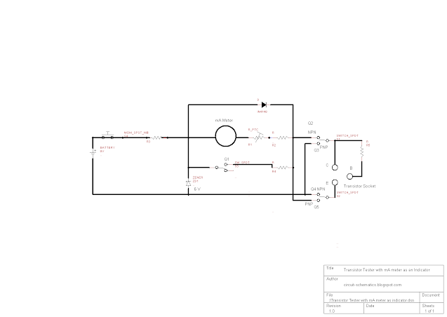
This Transistor Tester use for check whether the transistor tested in good condition or not. If the transistor tested still in good condition, mA meter pin will move , if the transistor tested not in good condition mA meter will not move or steady.
Switch S1 and S2, is sliding switch for setting whether the transistor tested is NPN or PNP.
S3 is sliding switch for set capacity power of mA, in this circuit we use 1 mA meter.
S4 is Push On Switch for giving voltage current to tested transistor.
When we want to tested NPN Transistor, Switch S1 and S2 we connect to Q2 and Q4, and press Push On Switch S4 to test the transistor . If the transistor in Good condition, the pin of mA meter will move to on a number of measurement. If the transistor in not works well , the pin of mA meter will not move .
AM FM Radio Kit, Good for Educational
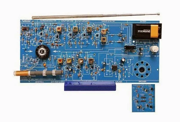 This Kit AM FM Radio, good for educational purposed for building AM FM Radio and for knowing more AM FM radio receiver .
 This Kit come with books as a guide for study more about the AM FM circuit, start from Audio Amplifier, AM Detector, AM IF, AM Amplifier, AM Mixer &
Oscillator, FM Detector, 1st FM IF, 2nd FM IF, and FM RF Stages.
Superheterodyne receiver of standard AM and FM broadcast frequencies.


- AM/FM Radio Kit (Combo IC & Transistor)
- Includes 64 page educational training guide
- with multiple choice questions and answers
- Training course of 56 pages is divided into 9 lessons: Audio Amplifier, AM Detector, AM IF, AM Amplifier, AM Mixer & Oscillator, FM Detector, 1st FM IF, 2nd FM IF, and FM RF Stages. Superheterodyne receiver of standard AM and FM broadcast frequencies. Makes an excellent classroom project. Requires 9V battery, not included.
Antenna Setup for Crystal Radio

Antenna for Crystal Radio can be setup in backyard or tall building, as high as possible , you can pick up much radio signal.


This is Tune Trapper Marine Antenna for Boat, also suitable for Fiberglass boat Car, RV, where ground plane no exist. You can install it in any place that suitable, no power need, no ground, no amplifier need. Made in USA and water resistant. Have Tested, have good reception in AM/FM Band. Just plug in to your antenna connection in your radio and Tune to FM 87.5 MHz-108 MHz.
This Tune Trapper is 1/2 Wave Helical Dipole
For Marine used, this antenna is sealed housing by PVC for defend from harsh marine use.This Tune Trapper dimension is 24 inch long and 1/2 inch diameter, complete with 6 feet 95% copper wire with standard motorolla connector, is USA handmade. Performance is guaranteed, and this Tune Trapper in bench tested, for make sure crystal clear reception.
Radio Crystal With One Transistor 2SB178
This Circuit is simple with One NPN Transistor 2SB178, Signal
selected from LC circuit and pick up with Germanium
Diode IN34A or IN60 or OA70 and Amplified with Transistor 2SB178 and with Earphone or Headphone with Resistant about 8-2000 Ohm.
The component list
COMPONENT '60 Turns' = L
COMPONENT '500 pF' = CV
COMPONENT 'IN34A/IN60/OA70' = D
COMPONENT '10 nF' = C
COMPONENT '5K6' = R
COMPONENT '2SB178' = TN
COMPONENT '4K7' = R
COMPONENT 'Earphone 8 - 2000 Ohm' = SPKR
COMPONENT '100uF' = CE
COMPONENT 'SWITCH' = SWITCH
COMPONENT '1.5V' = BATTERY
COMPONENT '' = GND
COMPONENT '500 pF' = CV
COMPONENT 'IN34A/IN60/OA70' = D
COMPONENT '10 nF' = C
COMPONENT '5K6' = R
COMPONENT '2SB178' = TN
COMPONENT '4K7' = R
COMPONENT 'Earphone 8 - 2000 Ohm' = SPKR
COMPONENT '100uF' = CE
COMPONENT 'SWITCH' = SWITCH
COMPONENT '1.5V' = BATTERY
COMPONENT '' = GND
Subscribe to:
Posts (Atom)