Antenna Handbook

How to pointing your dish network azimuth skew and elevation finder ?

Pointing Dish Network

Winegard(tm) Carryout(tm) Anser Antenna is a portable satellite system that required a user elevation setting to automatically acquire the desired satellite. 


Winegard Anser Antenna

As the user, you will need to know which satellite you would like to view and the corresponding elevation angle for that satellite. 

Under “Compatible Satellites,” different popular satellite options are outlined along with the programming offered via each satellite. 

Elevation and coverage maps are also included to help you determine the correct elevation angle and coverage for certain satellites.


The Anser Carryout Antenna for use with Dish Network and Bell TV, and DirectTV.
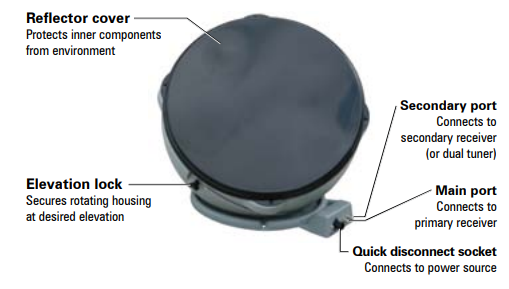

Parts Of Antenna


Antenna in Deployed Position


Antenna in Stowed Position


Simple step Installation Anser antenna 


  • Find elevation angle - via receiver menu or provided maps*. 

  • Hook up the antenna - manually set the elevation to the correct elevation angle for your area. 

  • Get to the signal meter-screen on your receiver. 

  • Plug in the unitthe unit will search and find the strongest signal. 

  • If the system stops-on a signal but is not on the desired satellite for viewing, the unit will move to the next signal found in 45 seconds. 
  • Once you have signal on your desired satellite - unplug the power to the unit. 

  •   Watch TV! 

How To Pointing Antenna ?

The Principle of Pointing an Antenna, you need only two information, The information about the Azimuth and the elevation number that point the antenna to the Satellite that will serve your receiver ? 

picture courtesy : promaxelectronics.com

See the picture describe the Azimuth the position of antenna from the North compass and the Elevation is the corner degree antenna from horizon . 

Just the simple like that...


*Elevation angles may not be displayed in the receiver menu for satellite 72° (recommended as a single satellite solution for DISH® HD programming) or 129°. 

If the elevation angle is not displayed in the receiver menu, use the provided elevation and coverage maps to find the elevation angle for your current location.

Compatible Satellites

For Dish Network

Set To :

72°: Eastern satellite, recommended for HD programming

129°: Western satellite, majority of HD programming

119°: Majority of std. programming

110°: Some standard programming, limited HD programming


Elevation Maps


How to use the maps ?

  • Determine which satellite you want to point at - Maps are provided for Dish 72, Dish 110, Dish 119, Dish 129, DirectTV 101, Bell TV 82, and Bell TV 91.
  • On the corresponding map-find your location.
  • Determine the elevation angle- closest to your current location.
  • Use this elevation angle to help point your antenna- Keep in mind that the elevation angles provided are approximate. 
  • If having trouble-locking onto signal with the elevation angle provided, try adjusting the angle ±2–3 degrees.


Example :


Your current location is in Colorado, and satellite is Dish 72 for HD Programming. Find your Elevation ?

Answer :

So look at Dish 72 Map below , for Colorado elevation is 33, so adjust your elevation to 33 degree from Horizon.

I attached a US map to make it easier to find your location and match the elevation map


Here the lists elevation maps 

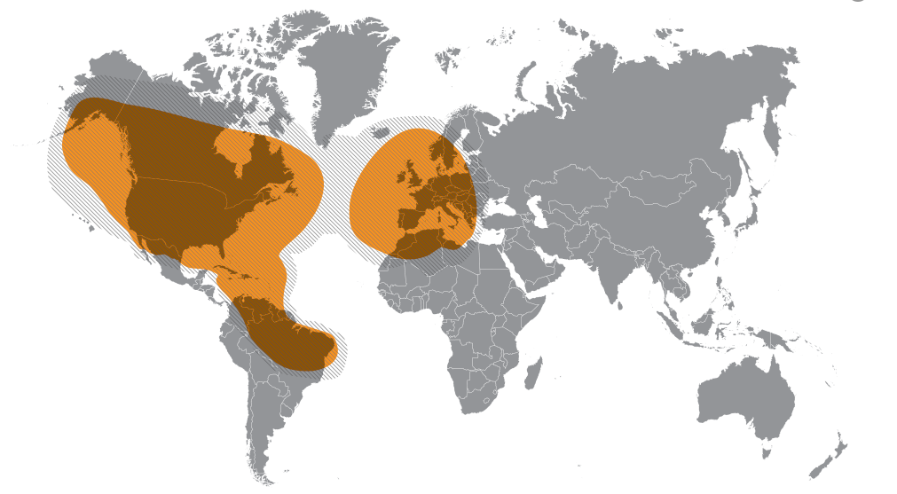
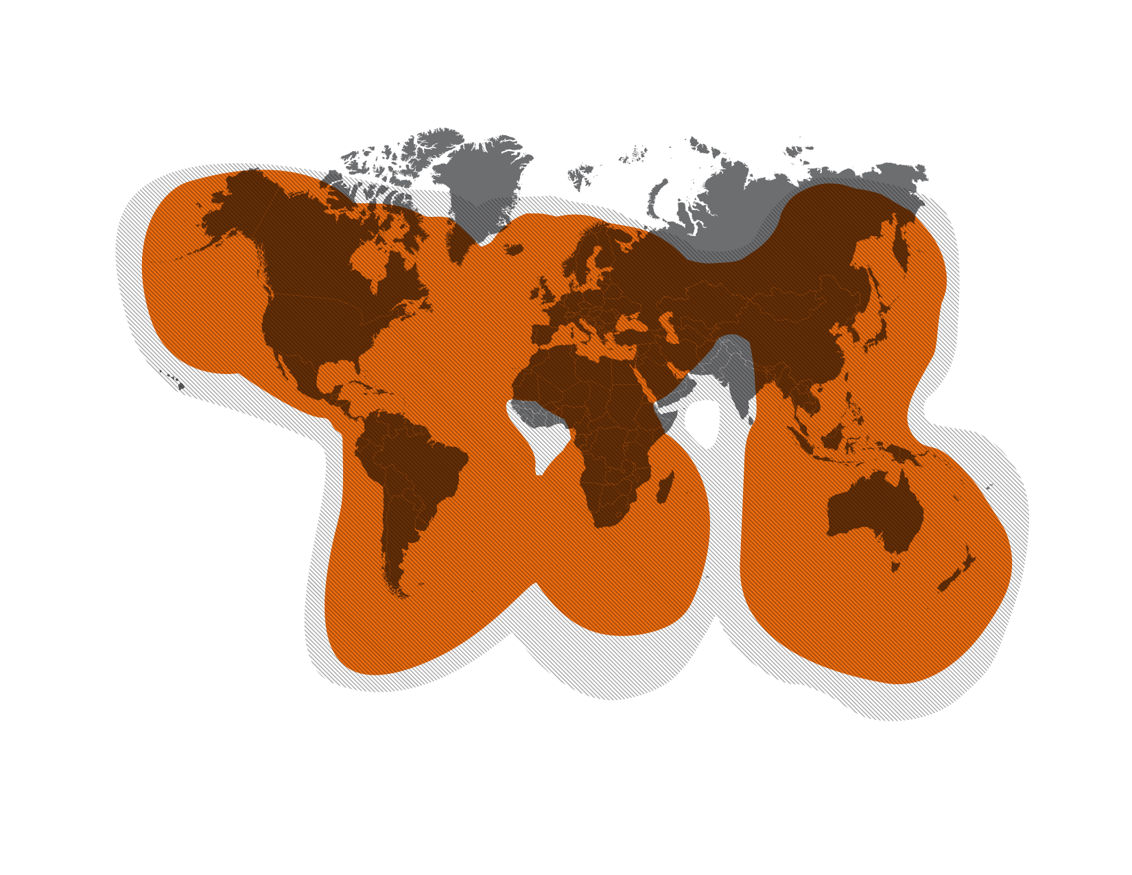
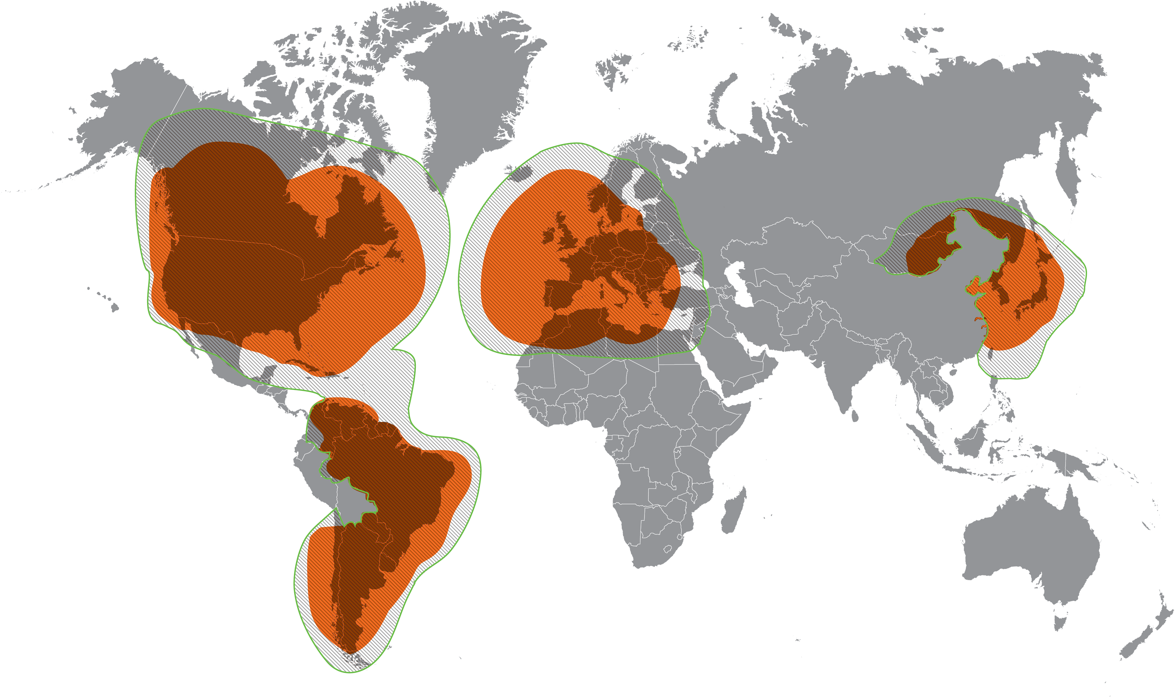
Maps For Dish Network


Maps for DirectTV


Maps for Bell TV


TIP 

The 72° satellite is recommended as a single satellite solution for DISH® HD programming. In the Northwest, the extremely low elevation angle may present issues in getting clear line-of-sight to the satellite. 

In those circumstances, use one of the western satellites (110°, 119°, or 129°). 


Note that the 72° and 129° satellites require an HD receiver. circumstances, use one of the western satellites (110°, 119°, or 129°). 


Note that the 72° and 129° satellites require an HD receiver. 

Here is Video Dish Azimuth and Elevation Pointing for your reference.
Reference : Winegard manual Dish Network

Globalstar Satellite Network

Globalstar
Globalstar is American Satellite Communication Service company operated 24 Low Earth Orbit (LEO)Network Satellites constellation. 

Services
Globalstar Satellite Network Services is Satellite Phone Communication, Satellite Data Communication, SPOT Satellite Messenger and Satellite IoT. 

Another LEO Satellite Services Company are Iridium, Inmarsat, Thuraya and Orbcomm.

Globalstar serve Industries from Oil and Gas, Maritime, Emergency, Forestry, Construction, Utilities. Globalstar have service in 120 countries.


Globalstar Products include :

  • Portable Telephones 
https://amzn.to/2RlYSYY

Coverage Map
  • Fixed Telephones, SAT-Fi2 Remote Antenna Station
Sat-Fi2 WiFi Hotspot Station

Coverage Map of Sat-FI2

  • Simplex Data Modems,
    Embedded Solution using Simplex Transmitter Unit (STX),Using the Globalstar Simplex data network, the STX3 allows information to be transmitted from areas well beyond the reach of reliable cellular coverage around the globe.

  • The STX3 provides additional opportunities to integrate satellite connectivity into products used for vehicle and asset tracking, remote data reporting and data logger reporting that have limited size requirements. 

  • Affordable pricing, low power consumption and its small size make the STX3 satellite transmitter a highly efficient device ready for integration in a wide variety of applications. 

  •  Simplex Transmitter Coverage Area Around The GlobeGlobalstar IoT Products Coverage Map
  • Duplex Data Modems, 
SPOT Gen3 provides employees with safe and reliable communication when working beyond the boundaries of cellular service

This rugged, pocket-sized device provides the ability to check in from any remote location. 

Utilizing GPS-enabled technology, emergency services can be notified, activated and dispatched to an exact location at the touch of a button.
 
Globalstar Spot X Coverage
  • Duplex Voice/Data Modules
  • GSP-1720 satellite data and voice module enables full two-way data and voice capability, allowing the development of new and creative tracking and monitor & control applications to full-featured fixed telephone service for remote areas.

    For Supervisory Control and Data Acquisition (SCADA) applications, the GSP-1720 Satellite Data/Voice Module (SDVM) can provide either Direct or Dial-up Internet as well as asynchronous computer to computer connectivity. 

  • These options provide communications with land and marine-based equipment, while complementing mobile and stationary field solutions. Mobile or stationary, the GSP-1720 helps you monitor, control or track assets remotely through the Globalstar satellite network - affordably and with low-power requirements. 


  • Another Service from Globalstar is Asset Management with Smart One Solar, SmartOne C as Asset Ready Tracket and Spot Trace as Theft Alert Tracking

FTTH Network Solution

FTTx Internet Network solution 

consists of 2, FTTH and FTTB.
For small office, home, or SOHO, or apartment building. 

We called it a basic FTTx network project, which is usually low cost and simple service providing etc. 

(courtesy fiberoptictel.com)

  • If a fiber is run to a panel inside each subscribers apartment unit (eg: Home or SoHo), it is FTTH.
  • If instead the fiber goes only as far as the apartment building’s shared electrical room (either only to the first floor or to each floor), it is FTTB.

The basic function of FTTH/FTTB broadband access solution, like data, or internet service, IPTV etc. (courtesy fiberoptictel.com).

How To Optical Fiber test Measurements Using OTDR ?

Optical fiber cables are tested for attenuation using the cut back method or back reflection method . The cutback method is mainly used in test at the manufacturing facility and the back reflection method is normally used in the field and in the manufacturing facility for some tests. An optical time domain reflectometer (OTDR) is the portable optical test set used in the field for pre- and post construction fiber measurements. The backscatter concept is illustrated in Figure 1


A lead-in or launch fiber is used to eliminate the effect of dead zone created from the OTDR fiber interface connector. A lead-in fiber is a fiber several hundred meters in length that connects the OTDR to the fiber being measured. It provides a useful fiber trace for the entire length of fiber under test. Since it provides backscatter power leading into and out of the initial fiber connection in the fiber undertest, a more accurate measurement of fiber length and total end-to-end loss can be made. The lead-in fiber is a commercially available OTDR accessory with a connector on one end to match the OTDR network interface and a connector on the other end to match the connector encountered on the fiber under test or in this case a bare fiber with a mechanical alignment fiber connector, such as an elastomeric lab splice. Lead-in fibers are useful to locate short distance faults and making loss/attenuation measurement in real time mode. This document explains howto use lead-in fibers.
One of the OTDR equipment come from Fluke Networks

Measurement Procedure.

Block Diagram 

This is a schematic diagram of testing optical fibers using an OTDR with a lead-in or a launch fiber.

Procedure 

Connecting Dummy Fibers / Pigtails to OTDR: Clean optical connector in end of lead-in fiber that will mate with the OTDR using isopropanol and lint free wipers. Connect it to the OTDR output so that a fiber trace can be observed. A square peak on the fiber trace (see Figure 3) will mark the start of the trace. Next to this peak OTDR traces should be a smooth with a continuous slope. Adjust the connector to obtain the OTDR trace as shown in Figure3.

DIY Six Stage Attenuator for High Frequency HF

If you have to deal with radio frequency more than very rarely, it is helpful if you can easily weaken the signals in discrete steps. 

So you can e.g. Bring the output signal of an HF generator to a different level than would only be possible with the generator's adjuster. 

There are many applications for a concealer when comparing or repairing receivers or with radio devices. Unfortunately, professional attenuator are quite expensive. 

Doing it yourself is worthwhile here because expensive electronics are not required
The Circuit Diagram of Six Stage Attenuator from Elektor Elektronic July Edition 2017 in Germany language 

Circuit Diagram


PCB Lay Out

Final Six Stage Attenuator Prototype with aluminum case


With Six Stage Switches for 0..31 dB in 1 dB Step
Prototype Final

Frequency Response 0....-31 dB