Optical fiber cables are tested for attenuation using the cut back method or back reflection
method . The cutback method is mainly used in test at the manufacturing facility and the back
reflection method is normally used in the field and in the manufacturing facility for some tests. An optical time domain reflectometer (OTDR) is the portable optical test set used in the field for pre- and post construction fiber measurements. The backscatter concept is illustrated in Figure 1

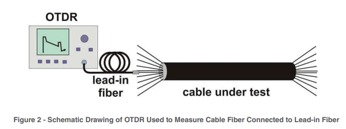


A lead-in or launch fiber is used to eliminate the effect of dead zone created from the OTDR fiber interface
connector. A lead-in fiber is a fiber several hundred meters in length that connects the OTDR to the fiber
being measured. It provides a useful fiber trace for the entire length of fiber under test. Since it provides
backscatter power leading into and out of the initial fiber connection in the fiber undertest, a more accurate
measurement of fiber length and total end-to-end loss can be made. The lead-in fiber is a commercially
available OTDR accessory with a connector on one end to match the OTDR network interface and a
connector on the other end to match the connector encountered on the fiber under test or in this case a
bare fiber with a mechanical alignment fiber connector, such as an elastomeric lab splice. Lead-in fibers
are useful to locate short distance faults and making loss/attenuation measurement in real time mode. This
document explains howto use lead-in fibers.
One of the OTDR equipment come from Fluke Networks

One of the OTDR equipment come from Fluke Networks
Measurement Procedure.
Block Diagram
This is a schematic diagram of testing optical fibers using an OTDR with a lead-in or a launch fiber.

Procedure
Connecting Dummy Fibers / Pigtails to OTDR: Clean optical connector in end of lead-in fiber that will
mate with the OTDR using isopropanol and lint free wipers. Connect it to the OTDR output so that a fiber
trace can be observed. A square peak on the fiber trace (see Figure 3) will mark the start of the trace.
Next to this peak OTDR traces should be a smooth with a continuous slope. Adjust the connector to
obtain the OTDR trace as shown in Figure3.

No comments:
Post a Comment