Omnidirectional Dipole HDTV Outdoor Digital Antenna

Now We look at this Omnidirectional Antenna from Channel Master.


Features

  • Channel Master with Digital Reception Range: 50+ Miles (360° Omnidirectional) is approximately 80 km, it is dipole Antenna in design.
I Think is suitable if you near the city or around the TV Stations Mast . And you can predict how long the distance your house from the TV Stations. If more 50 miles , I think this products is not for you.
  • Compatible with all HDTV's and 4K TV's
This means this product is compatible with digital TV Channel. 
  • Includes: Mounting Bracket for Mounting to a Wall, Mast Pole or an Existing Satellite Mount , and U bolt
  • Designed for Indoor or Outdoor Use on Roof, Attic, or RV
  • Easy to Install

Price

The Channel Master Omnidirectional Indoor/Outdoor HDTV Antenna Sale for $ 69.00.
With This Price , you will get Antenna and  Mounting Bracket , the price quite fair enough.

This Antenna if we look from physical views, is dipole antenna, And I do not see the information how much the dBi The Reception of Antenna and Also the dimension of antenna information not included. High dBi Rating means = further distance covered. So, with 50 miles distance covered reception is quite long distance around 80 km.


Pros 

  • Antenna Install Can Rotated Manually
  • Antenna Install can Pointing Manually for Better Reception
  • Install in Attic without Amplifier with 40+ channel with fairness reception.
  • Good Reception for Distance under 50 miles without amplifier needed UHF/VHF reception TV Networks
Cons
  • For more than 60 miles + Amplifier Signal Bar between 2-5 not for All Channels, amplifier needed

Installation

Channel Master Omnidirectional Antenna Indoor Outdoor HDTV Install on Direct Dish  

Channel Master Antenna Installation and signal strength

Channel Master Omnidirectional Antenna Assemble Video


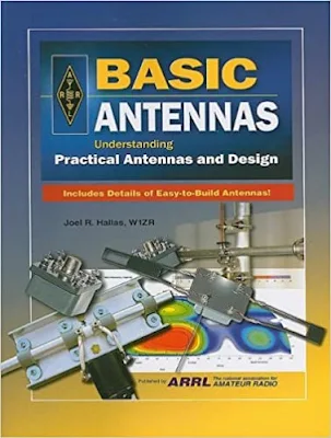
Arrl Antenna Book Review : Basic Antennas, Understanding Practical Antennas and Design

This Book written by Joel R. Hallas cover Basic Antennas Design and Practical with 26 Chapter and 2 Appendix  , suitable for college,student, and hobbyists and other enthusiasm in Antenna field.

Very good book for Professional and Amateur Enthusiasm for reference DIY Antennas , and how to design and build Do It by Yourself.

From Chapter 1, discuss about what an antenna is ? , the concept of antenna with Practical understanding and example in Practical and real life. 
Chapter 2, Half Wave Dipole Antenna in Free Space 
Chapter 3, The Field from a Dipole Near The Earth
Chapter 4, The Impedance of Antennas
Chapter 5, Transmission Lines
Chapter 6. Making Real Dipole Antennas
Chapter 7, The Field From Two Horizontal Dipoles 
Chapter 8, The Field From Two Vertical Dipoles
Chapter 9, Transmissions Lines as Transformers
Chapter 10, Practical Two Element Antenna Arrays 
Chapter 11, Wideband Dipole Antennas
Chapter 12, Multiband Dipole Antennas 
Chapter 13, Vertical Monopole Antennas
Chapter 14, Arrays of Vertical Monopole Antennas
Chapter 15 Practical Multielement Driven Arrays
Chapter 16, Surface Reflector Antennas
Chapter 17, Surface Reflector Antennas You Can Build
Chapter 18, Antenna Arrays With Parasitically Coupled Elements
Chapter 19, The Yagi-Uda or Yagi, Parasitically Coupled Antenna
Chapter 20, Practical Yagis for HF and VHF
Chapter 21,Log Periodic Dipole Arrays
Chapter 22,Loop Antennas
Chapter 23, Loop Antennas You Can Build
Chapter 24, Antennas for Microwave Applications
Chapter 25, Vehicle Antennas
Chapter 26, Antenna Measurements
Appendix A Getting Started in Antenna Modeling with EZNEC
Appendix B Using Decibels in Antenna Calculations Index

Make A Simple Halfwave Dipole Antenna for TV

In this article I will show you how to make simple a halfwave dipole antenna for home TV reception using 2 radiators , consist of two 1/4L coaxial cable and feed point .
The video for how to make this simple antenna also you can watch on my youtube channel.

Digital TV frequency band is 470-800 MHz , depends on your country and location, you can adjust with your own frequency used. So, based on that frequency , we will design the radiator Length (L) of Antennas, as in Simple A Halfwave Principle Antenna Design .


For High Frequency, we used formula :

                                                                 L = 468/Fmhz 

Center Frequency of 470-800 MHz is 635 MHz

                                                                L = 468/635
                                                                 
                                                                   = 0.737 ft

                                                                   = 0.113 meter  (approximately)
                              
                                                                   = 11.3 cm

                                                          1/2L  = 5.65 cm

So, we will make 2 radiators using coaxial cable with length 5.65 cm each

Wire Direction Antenna

A directional antenna has the ability to enhance reception of desired signals, while rejecting undesired signals arriving from slightly different directions. Although directivity normally means a beam antenna, or at least a rotatable dipole, there are certain types of antenna that allow fixed antennas to be both directive and variable.


See Chap. 7 for fixed but variable directional antennas and Chap. 11 for fixed and non-variable directive arrays. Those antennas are transmitting antennas, but they work equally well for reception. This section shows a crude, but often effective, directional antenna that allows one to select the direction of reception with pin plugs or switches.

Consider Fig. 13-10. In this case, a number of quarter-wavelength radiators are fanned out from a common feedpoint at various angles from the building. 

At the near end of each element is a female banana jack. A pair of balanced feedlines from the receiver (300-Ω twin lead, or similar) are brought to the area where the antenna elements terminate. 

Each wire in the twin lead has a banana plug attached. By selecting which banana jack is plugged into which banana plug, you can select the directional pattern of the antenna. If the receiver is equipped with a balanced antenna input, then simply connect the other end of the twin lead direction to the receiver. 

Otherwise, use one of the couplers shown in Fig. 13-11. Figure 13-11A shows a balanced antenna coupler that is tuned to the frequency of reception. 

The coil is tuned to resonance by the interaction of the inductor and the capacitor. Antenna impedance is matched by selecting the taps on the inductor to which the feedline is attached. A simple RF broadband coupler is shown in Fig. 13-11B. 

This transformer is wound over a ferrite core, and consists of 12 to 24 turns of no. 26 enameled wire, with more turns being used for lower frequencies, and fewer for higher frequencies. Experiment with the number of turns in order to determine the correct value. 

Alternatively, use a 1:1 balun transformer instead of Fig. 13-11B; the type intended for amateur radio antennas is overkill powerwise, but it will work nicely.


Field Strength Meter Circuit Diagram For CB Radio 27 MHz SSB

This meter can often help you get better signal transfer between antenna and transceiver than an SWR meter. 
 

The Circuit 

You can make your own field strength meter for just a few dollars by following this circuit diagram. Wiring is not critical , but use metal housing.