Broadband Antenna with reflector

In Yagi antennas, reflector antennas and in-phase excited antennas are suitable for amateur production.

a) Broadband dipole with angular reflector and broadband reflector
Due to the large feedback factor, this antenna is (Fig. 160) Suitable for places with a medium and strong signal, disturbed by reflections from rearward direction, ie especially to urban districts with height segmentation development. The radiation diagram in Fig. 160c applies to the frequency 730 MHz, at which this antenna has the highest gain. The return factor is in the whole scope IV. and V. television band almost uniform. The electrical parameters are shown in Fig. 161. Fig. 162 is a view of the actual embodiment antennas with angled reflector.

b) Excited full-wave floor system for channels Nos. 21 to 81


This antenna (Fig. 163) is very suitable for amateur construction, because is not as demanding on accuracy as Yagi antennas and always gives good results. The reflector wall can be either made of mesh with a mesh size 20 X 20 mm (Fig. 163a), or can be made according to Fig. 163b


In both cases, however, all the wires crossing each other are necessary solder with tin or tin the whole reflector wall in fire (galvanic tinning is not enough). The electrical values ​​are almost equal in the whole band


specific (see also Fig. 171). The antenna is also suitable for places with inhomogeneous ones field, is significantly less sensitive to the quality of the incident field than antennas Yagi type.


The gain of an excited whole-wave floor system can be maintained while maintaining the basic
increase by about 2 dB by adding a series of directors to each emitter (Fig. 164). Director carriers are threaded at both ends, enabling easy installation even in an already finished antenna.


A further increase in gain is achieved by arranging four antennas in the system (Fig. 165). The spacing of the antennas in the axis of the system is chosen so that the distance between individual emitters was constant. The reflectors of these antennas therefore overlap, it is advisable to shorten them accordingly. It is advisable to merge the antennas in series with a parallel connection .


(source : translated from Anteny by Tomas Cesky)

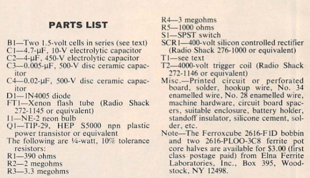
A Strobe flasher for bike indicator

Simple circuitry allows the project to be built at low cost in a lightweight, compact
package that can be secured to the bicycle or the rider's belt. 
The light from this circuit uses a xenon tube to generate a bright flash that can be
seen from a great distance - but is not intense enough to destroy a driver's night vision.

Circuit 


Parts Lists

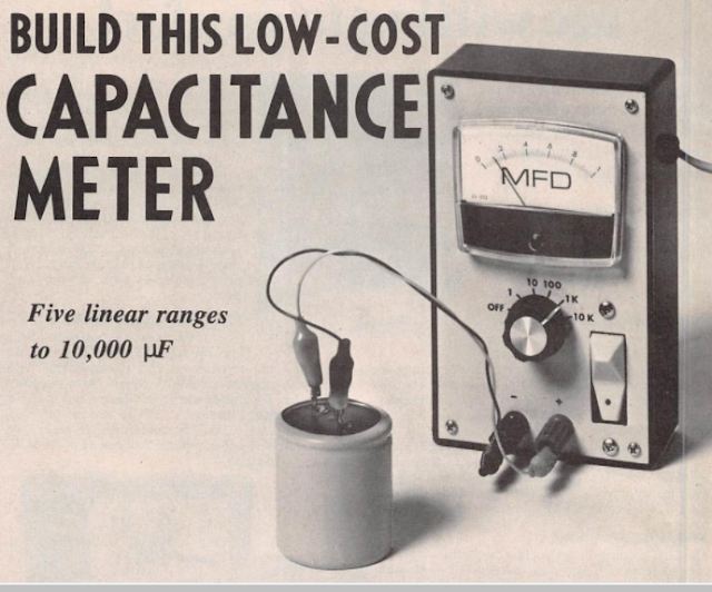
Build your own this low cost analog capacitance meter


When a capacitor is connected to a constant-voltage source through a resistor, the charge on the capacitor increases exponentially. If the source supplies a constant current, however the charge on the capacitor increases linearly. This linear charging principle is used here in the design of capacitance meter which will measure values outside the range of most such meters. 

By using a constant-current source, the meter determines the time it takes to match the charge on the unknown capacitor to a known reference voltage. The meter has five full scale range o 1, 10, 100, 1000, and 10,000 uF.on the 1-uF scale , values as small as 0.01 uF can be read easily.

The Circuit 


Power Supply


Parts List


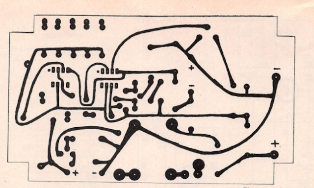
PCB Layout


Component Layout 


Prototype:


source :  Electronic Experimenters Handbook 1980 edition 

Best TP Link Archer Wireless Router Series

We pick 10 best TP-Link Archer Series . TP-Link Technologies Co., Ltd., is a Chinese manufacturer of computer networking products based in Shenzhen, Guangdong, China.

1.  TP-Link AC1750 Smart WiFi Router (Archer A7)

Dual Band Gigabit Wireless Internet Router for Home, it Works with Alexa, VPN Server, Parental Control, QoS

With parental controls and guest access.Keep your family safe and devices secure with advanced WPA/WPA2 wireless encryption.

Delivers Up to 2,500 sq.ft. exceptional WiFi coverage  throughout your home as three high-gain antennas and strong amplifiers connect every device—from the living room to the backyard. Check It Out

White LED Lamp Circuit

Make  this  solid-state pocket torch using a few of these white LEDs. The simplest approach is naturally to use a separate series resistor for each LED, which has an operating voltage of round 3.5 V at 20 mA. Depending on the value of the supply voltage, quite a bit of power will be lost in the resistors. 

The converter shown here generates a voltage that is high enough to allow ten LEDs to be connected in series. In addition this converter supplies a constant current instead of a constant voltage. 

A resistor in series with the LEDs produces a voltage drop that depends on the current through the LEDs. This voltage is compared inside the IC to a 1.25 V reference value, and the current is held constant at 18.4 mA ( 1.25V devided by 68Ohm)
The IC used is one of a series of National Semiconductor 'simple switchers'. The value of the inductor is not critical; it can vary by plus or minus 50 percent. 220 uH coil at 3.5 A is good choice. Almost any type of Schottky diode can also be used, as long as it can handle at least 1 A at 50 V. The zener diodes are not actually necessary but they are added to protect the IC. If the LED chain is opened during experiments, the voltage can rise to a value that the IC will not appreciate.

Circuit


PCB Layout


Component Layout


Parts Lists


source ; Elektor