The Best VK3UM downloads

VK3UM downloads -  was a software develop by Dough McArthur,Doug VK3UM. For VK3UM Downloads please click here    , VK3UM downloads software consist of EME Calculator [EMECalc] , EME Planner, VK3UM Libration Calculator [LibCalc], VK3UM Electro Magnetic Radiation Calculator [EMRCalc], Atmosphere , Atmosphere calculates the absorption attenuation at Microwave frequencies for both terresttail and slant paths for Amateur frequencies from 10-241 GHz. and VK3UM Noise Source Planner, VK3UM 4 Stage Inter Digital Filter Design [IDF], Transmission Impedance Calculator, VK3UM Auto Track, VK3UM Sun Noise and Measurements.


The software provides the ability to  :
 • select the Radiation Limit to suit your Governing Authority’s Standard. 
 • select the transmission frequency (1.8MHz to 49GHz).  
 • vary the transmitter output power and associated feed losses.
 • select the transmission mode duty factor and averaging period characteristics.
 • select ground reflection factor if required
 • vary the antenna size and efficiency of a Parabolic reflector or select single or multiple yagi arrays  
 • select pre programmed rectangular aperture antennae types for HF (High Frequency) calculations or adjust antennae gain as necessary.
 • vary the height of the HF antennae and display the resultant on axis Exclusion Zone. (bore sight direct line distance)
 • select metric or imperial display presentation.  
 • save and recall user specific preference configurations as required.  
 
The RF Radiation Calculator provides the On Axis Exclusion Zone (General Public), for both near and far field radiation levels, is displayed in both text and graphical (RFGraph) formats. 
 
The System Performance Calculator will simultaneously display both S/N of the Moon Echo and the Sun and Cold Sky to Ground Y factor levels for variables generally not provided in other calculators. These include the added ability to vary; • 10.7cm Solar flux. 
• dish mesh characteristics.
• derived spill over and feed through values. 
• Preamplifier and pre first amplifier gain and loss characteristics. 

Through out the World many Government Authorities have indicated that they are proposing to implement, or are in the process of implementing mandatory standards of radiation limits pertaining to the Radio Amateur Service.  Because of the nature of EME (Earth-Moon-Earth) and other Amateur communications, radiated power levels can be quite high and may, under certain situations, pose a radiation hazard. This software calculates the level of RF Radiation and specifically addresses the near field radiation characteristics of a circular aperture radiating antennae. (RFGraph.exe). This characteristic could be most significant in being able to demonstrate that an EME Station is able to meet Governing Authority’s radiation limits. 

VK3UM Opening Screen

VK3UM HF Option


Program Aim 

The prime purpose of the software is to define the Radiation Level of the On Axis Exclusion Zone, commensurate with the stations effective radiated power, mode of operation and antennae gain. The secondary purpose is to provide the most accurate calculations for the EME budget, Sun Y factor (relative to the solar flux), and Sky (Cold) to ground Y factor.  The user has the ability to vary all or any of the interacting factors and determine, with a high degree of accuracy, your system’s performance. 
 
 
Screen Options
 
The first time the program is run the default parameters as listed in Part 6 of this document will be displayed.  

The VHF-SHF Screen provides access to the Parabolic Reflector (default) and the yagi Array. To select the yagi array click on the button to the left of the display. Similarly to reselect the Parabolic Reflector display click on its button.  

The HF Screen may be selected by clicking on the small button (HF) in the bottom right hand corner of the frequency panel. The options available within this screen may be selected by clicking one of the available options (Low Gain Antennae, Yagi Array or Parabolic Reflector). Access to all the Low Gain Antennae options may be gained by clicking on the associated panel (it will high light in white) and further choose other options by use of the up/down arrows . To return to VHF-SHF screen click on the SHF button.  

Transmission Mode Form Factor options should be selected in accordance with the Standard chosen. In the case of the FCC OET Bulletin 65 they select Carrier or 100%.  

Six Minute Period Average options should also be selected in accordance with the Standard chosen. In the case of the FCC OET Bulletin 65 they select Conversational or 100%.  

Ground Reflection. Select his option where required. This will depend upon the situation under question and should be applied as appropriate. In the case of the FCC OET Bulletin 65 they stipulate this option (in most instances) as a worse case scenario.  

RF Radiation Standards. Three are provided as indicated plus a variable facility to allow for any other Radiation Limit. Many Countries have as yet to define their Standard and the variable option is provided for such eventualities.  

Transmitter Power. Levels from 1-9999 are provided to cover most Amateur situations.  

Transmission Loss. Actual power measured at the radiator. Adjust to suit your particular situation. Remember to include all feed, relay, balun, and divider losses as appropriate.  

Metric/Imperial Button. Selecting either will reflect on all displayed calculations. Note that this function is a ‘stored parameter’.  

System Performance Calculator. There are 14 variables that the user may adjust to suit their situation. The ability to ‘reverse engineer’ your results provides the user with a system analysis tool of considerable effectiveness. 

 File Handling Options  

The Data button provides access to data file management options. 


Save data allows the user to store as many files, with whatever file name you choose (extension is set to *.dug) .  Get Data allows the user to recall the file as stored above. 

Cancel aborts the process and returns the user to the main screen. 
 
Note. 1 All the screen variables available to the user are stored. 2. You may also cancel the save or get file options by using the cancel option when in these screens. 


Default Option allows for the retrieval of user defined set up parameters. When the program is first initiated the parameters displayed should be changed to suit the users preferred options. They should be stored as ‘default.dug’. This file will be recalled automatically when clicking on the default button. If the file has not been created then the user will receive an error message warning of the requirement. as well as all the other  variables of frequency, sky temperature, LNA, receiver noise figure, band width and system loss factors. The calculator will provide most accurate data for typical installations and allow the user to define and analyse the operational capabilities of the station. 


In the Next Articles I will write about Default Parameters , Parameters Description, Calculation Methods and Display Presentation.

Radiation pattern with matlab

patternCustom

Plot radiation pattern using spherical coordinate system (phi and theta angles)

Syntax
patternCustom(magE,theta,phi)
patternCustom(magE,theta,phi,Name,Value)
hplot = patternCustom(___)

Description
patternCustom(magE,theta,phi) plots the 3-D radiation pattern of an antenna magnitude, magE over the specified phi and theta angle vectors.

hplot = patternCustom(___) returns handles of the lines or surface in the figure window. This syntax accepts any combination of arguments from the previous syntaxes

Examples

Visualize Radiation Pattern From Antenna Data File
Consider a helix antenna data file in .csv format. This file contains the magnitude of the antenna directivity in phi and theta angles. Read The File 
Command : openExample('antenna/VisualizeRadiationPatternFromAntennaDataFileExample')

helixdata = csvread('antennadata_test.csv',1,0);

Use patternCustom to extract the magnitude of directivity, and the phi, and theta angle values. Plot the 3-D polar radiation pattern.

patternCustom(helixdata(:,3),helixdata(:,2),helixdata(:,1));

Visualize Radiation Pattern From Antenna Data File

Visualize Radiation Pattern From Antenna Data File


Use the same data to plot the 3-D rectangular radiation pattern.


figure
patternCustom(helixdata(:,3),helixdata(:,2),helixdata(:,1),...
 'CoordinateSystem','rectangular');

3D Rectangular radiation Pattern


Visualize 2-D Radiation Patterns of Helix Directivity


Calculate the magnitude, azimuth, and elevation angles of a helix's directivity at 2 GHz.

Command :

openExample('antenna/VisualizeRectangularAndPolar2DRadiationPatternOfHelixExample')

h = helix;
[D,az,el] = pattern(h,2e9);

Here, az = the angle from the positive x-axis to the directivity vector's orthogonal projection onto the xy plane, moving in the direction towards the y-axis.

el = the angle from the directivity vector's orthogonal projection onto the xy plane to the vector, moving in the direction towards the z-axis.

Extract theta and phi angles of the directivity magnitude.

phi = az';
theta = (90-el);
MagE = D';

Plot 2-D phi slice of the antenna in rectangular coordinates.

figure;
patternCustom(MagE,theta,phi,'CoordinateSystem','rectangular',...
    'Slice','phi','SliceValue',0);

Plot 2-D phi slice of the antenna in rectangular coordinates.


Plot 2-D phi slice of the antenna in polar coordinates.


figure;
patternCustom(MagE, theta, phi,'CoordinateSystem','polar',...
    'Slice','phi','SliceValue',0);

Plot 2-D phi slice of the antenna in polar coordinates
Plot 2-D phi slice of the antenna in polar coordinates.


rf bnc 50 ohm attenuator

rf bnc 50 ohm attenuator


rf bnc 50 ohm attenuator

Attenuators - Interconnects PADS BNC 50 OHM BNC(M) (F) 20db - 

Is 20db enough attenuation to reduce 1W output to 0.5W ? 
20dB for this attenuator provides drop of voltage 10 times into 50 Ohms load. The power which is V^2/R will drop 100 times accordingly . The difference between 1 watt and 0.5 watts is 3 db. A 20 db attenuation is 1/100. 1 watt input gives 0.01 watt output. It will reduce your 1 Watt to .01 Watt. If you really need 0.5 Watt , then you need a 3 DB attenuator. It goes loke this: 3 db = half the power; 6 db = one fourth the power; 9 db = one eighth of the power; 10 db = one tenth of the power; 20 db = one one-hundreth of the power.  Said another way: for every 3 db of attenuation reduce the power by one-half. For every 10 db reduce the power by a factor of ten A 3db drop is half power.

What's the working frequency range of this attenuator? I need one working between 0.5 and 3 MHz with minimal distortion of the waveform.
I use them on 490MHz all the way to 875MHz, don't see distortion on waveform but I mainly use them to drop the signal so I don't overload enritsu or pathtrax. 

What is the maximum power input in Watts for this attenuator?
Max power input isn't indicated on the attenuator itself, but I've been running 1/2W through it without any problems so far.

will this attenuator work @ 30mhz and below ? I want to attenuate the input on a spectrum analyzer for use on the HF bands
You are looking at a resistive Attenuator. Should work all the way down to DC as long as you keep the power level low. At the upper frequency range you are limited by the BNC connection but should be good to 1GHZ.


Find The Best Guide to Indoor and Outdoor TV Antennas


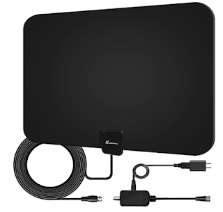
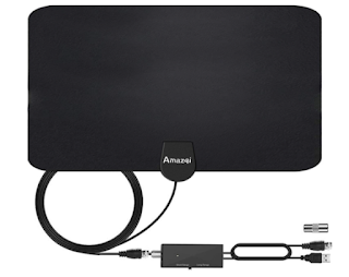
Indoor Antennas for receiving DTV 

(Note: An auction of spectrum that had been licensed to broadcast television stations operating on UHF TV Channels 38-51 resulted in many TV stations on these channels transitioning to other channels. Almost all of the TV stations affected finished transitioning in July 2020.) 

To receive DTV signals from all stations in the area, your antenna needs to be able to receive both VHF channels (channels 2-13) and UHF channels (channels 14-36). 

Some antennas only provide good reception of VHF or UHF channels, but not both. For example, indoor "rabbit ears" usually need to be augmented with an additional "wire loop" or "bowtie" antenna (see images on the next page) in order to pick up signals on UHF channels. 

Many of the antennas being sold as "HDTV Antennas" perform best at receiving UHF signals, but perform less well receiving VHF channels. Check with retail consultants and consumer websites to make sure that any antenna you choose provides good reception of both VHF and UHF channels. 

Even if you use a digital-to-analog converter box, you will still need to use an antenna to receive DTV signals. Digital-to-analog converter boxes do not contain additional antennas or signal amplification.

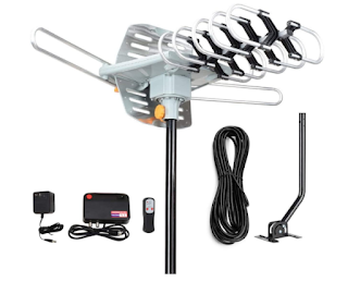
Antennas for reception in different signal conditions 


The antennas on the next page will work for the indicated signal strength in most instances, but may not work in all cases. 


The type of antenna needed at a specific location may vary depending on geographic location, the height at which the antenna is used and other local factors such as nearby buildings, trees, terrain or home construction. 

Generally, outdoor antennas will get better reception than indoor antennas and are strongly recommended for the most reliable reception.

If your home near the TV Broadcasting Station and not much blocking obstacles such high building and the TV signals is Strong Use Circular Loop and Dipole Antenna such Rabbit Ears Antenna. 


Best Practical Antenna HandBook by joseph J. Carr for Hobbyist, Students, and DIYers

  • Are you looking for practical antenna book ?
  • tired reading theory from other books and literature
  • are you looking for antenna books that can implemented for your business , companies, and hobbyist ?
Now you can get the practical antenna books in here
 
from the practical electronics engineer/antennA Hobbyist  that have more 35 years experienced in antenna field/ master and guru in antenna field

joseph j. carr


BEST HANDBOOK FOR UNDERSTANDING PRACTICAL ANTENNA - ORDER IT NOW

Practical Antenna HandBook 5/e 5th Edition - This Book is a practical antenna handbook ,by Joseph J. Carr , a book that explains antennas in terms of theory and practical examples to apply, suitable for Hobbyist, Students, and DIYers. Practical Antenna Handbook is a thick volume that tries - mostly successfully - to balance technical detail against practicality.


The most popular book on antennas ever written and unquestionably the world's favorite antenna book, Joseph J. Carr's Practical Antenna Handbook, fourth Edition and Fifth Edition. 

Joseph J. Carr  

Is was a military electronics technician and the author of several popular electronics books, including McGraw-Hill’s Secrets of RF Design, Third Edition and Old Time Radios! Restoration and Repair. He wrote a monthly column for Nuts & Volts magazine.
 

George W. (Bud) Hippisley,

Is  W2RU, earned his BSEE degree from MIT, and was formerly chief operating officer for a major supplier of electronics to the cable TV industry. A long-time active amateur radio operator who has won or ranked nationally in many competitive on-the-air operating events, he has given talks on the basics of antennas and ionospheric propagation to radio clubs and other groups for more than 35 years.

Several article from Practical Antenna Handbook you can find in this blog, and this This intended to let the reader knows the contents of this book, this book combines theory and practice very well and clearly, suitable for hobbyists, scientists, college students, or anyone interested in antenna

In this book you will learn about Introduction to radio communication, radio wave propagation, Antenna Basics , dipole antenna, standing waves antenna, transmission lines, impedance matching, Antenna Arrays, Antenna Gains, High frequency Antennas, Wire Loop Antennas, Multiband Antenna , Tune able Antenna, Wire Antenna, Yagi Uda Antenna, Microwave Antenna, Mobile Antenna, Marine Antenna, VHF Antenna, UHF Antenna, Smith Chart, Antenna Software , Tower Antenna and etc. 


The ARRL Antenna Book for Radio Communications has everything you need to design your own complete antenna system. Since 1939, it has maintained its place at the forefront of Amateur Radio technology a single resource covering antenna theory, design and construction, and practical treatments and projects. In this edition, The ARRL Antenna Book describes hundreds of antenna designs: wire, vertical, portable and mobile, and new high-performance VHF/UHF Yagi designs.

Radio amateurs continue to make contributions to the state of the art in antenna design and construction. The available tools have grown in sophistication by leaps 
and bounds over the past years. Antenna modeling with the low-cost or free programs available to amateurs has completely changed antenna design and development. 
A large set of antenna models designed for use with EZNEC 6.0 demo software is included.

Updated to reflect the latest advances and technologies, this 23rd edition is full of antenna designs pioneered by dozens of radio amateurs:

New Projects: Multiband HF antennas from 160 through 10 meters, A simple omnidirectional satellite antenna system, More popular Moxon antenna projects on CD-ROM, 
Stealthy and portable antenna designs for home and away.


Radio Experimentation, Discovery, and Achievement. The ARRL Handbook for Radio Communications is a complete reference and guide to radio technology principles and practices. Since 1926, The ARRL Handbook has been a trustworthy source of introductory, applied, and theoretical information. 

Now in its 96th edition The Handbook continues to advance the pursuit of experimentation and innovation by radio amateurs and professionals. Each edition contains new and useful material to support Amateur Radio activity from the traditional short- and long-wave frequencies through microwaves! Key Topics Radio electronics theory and principles Circuit design and equipment Radio signal transmission and propagation Digital and analog modulation and protocols Antennas and transmission lines Construction practices.

Who reads The Handbook? Amateur Radio operators, or hams; professional wireless communication engineers and system designers; electrical engineers; students and instructors of engineering, physics, and geoscience. 

Always Updated! New Projects and Content Simple SLA Float Charger project by John Boal, K9JEB Amateur Radio Data Platforms by Paul Verhage, KD4STH and Bill Brown, WB8ELK The latest information on WSJT-X digital modes by the WSJT team Filter and circuit design software by Tonne Software and Jim Tonne, W4ENE Low-Noise VHF and UHF Oscillators by Ulrich Rohde, N1UL, and Ajay Poddar, AC2KG Update on Solar Cycle 24 by Carl Luetzelschwab, K9LA Updated SSTV practices and technology by Larry Peterson, WA9TT.

Designing dual-band loaded dipoles by David Birnbaum, K2LYV Latest transceiver survey by Joel Hallas, W1ZR Plus, new component tables, reference articles, material characteristics, and guidelines for SDR design. Download Included: eBook and Supplemental Material Download the fully searchable digital edition of the printed book, as well as expanded supplemental content, software, PC board templates, and other support files.