The Best Indoor HDTV Antenna - As we know, cable TV, streaming TV services, and satellite TV , as Hulu, Disney+, HBO, NetFlix, and etc, require us to pay a subscription fee every month, and burden the monthly bill for each house, and many people have left it to switch to Aerial TV and Digital TV services which currently have a variety of programs.
 |
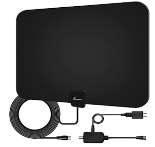
| Indoor HDTV Antenna |
As consumer reports after tested many digital Indoor HDTV Antenna , tested with different distance and location from many customers, I picks several popular brands Indoor HDTV Antenna for your reference before purchase.
Consumer rated recommendation the antenna based on easy installation, easy setup and get VHF and UHF band, also pick up almost all channel.
Indoor HDTV Antenna will reduce Your Monthly TV Bill
You can now experience HDTV in the highest quality picture and sound available. Over-the-air broadcasts are transmitted in crystal clear Full HD 1080; far less compressed than what cable and satellite offer. Many local broadcasts are digitally aired in 5.1 Surround Sound giving you the ultimate sound stage for watching live television.
With a digital antenna you can receive free local news, weather, kids shows, sports, cooking, shopping, and sitcoms from networks like ABC, NBC, CBS, FOX, PBS, CW, ION, and much more with no cost or contracts. And broadcast TV won't be interrupted from service drop outs (satellite). Quick fact: local sports are broadcast free over-the-air. You just need an antenna.
For those who still want to see local TV programming and don't want to pay subsciptions cost, Indoor HDTV antennas brands such as Clear Stream, RCA, Winegard, Mohu, 1ByOne are the best choice for TV at home

Price : $82.00 from Amazon
Specifications :
- Flexible Antenna Material
- Amplifier Included
- Detachable cable
- Long range upto +50 miles
- Easy Installation
 |
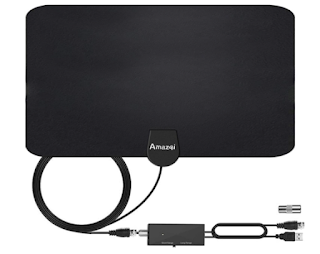
| RCA Ultra-Thin, Multi-Directional Indoor HDTV Antenna |
Indoor HDTV Antenna with Patented, 360º multi-directional design eliminates need for constant adjustments. RCA's advanced SmartBoost technology amplifies weak signals to deliver the most channels possible while filtering out false signals.
Price : $35.99 from Amazon
Specification
- 60 mile range reception
- Amplifier Included
- Flexible Antenna Material
- Easy Installation
 |
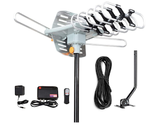
| Winegard Flatwave Amped Pro HDTV Indoor Antenna |
App-enabled to capture the most free TV channels. This indoor HDTV antenna is powered with a technology duo, an amplified Bluetooth signal meter, and Clear Circuit technology to give you quick access to all the channels in your area. The digital amplifier embedded in the antenna boosts available signals by 100%.
Sort by signal strength or fine-tune to get the channels you want
Price : $104.62 from Amazon
The FlatWave Amped Pro is the only antenna with an actual signal meter integrated into the antenna to provide the best possible customer experience when installing. The Flatwave Amped Pro uses a built-in tuner to get real-time signal data
Specification
- Capture signal more than 60 miles away
- Built-in Clear Circuit Technology boosts reception, cuts dropout, and clears pixelation.
- Ultra low noise (1 dB) digital amplifier is attached directly to the Antenna
- Bluetooth Signal Meter and Integrated Channel Finder
 |
| 1ByOne Amplified Indoor Digital HDTV Antenna |
High Performace with on Budget Price , high gain Antenna almost 28dB
Price : $27.99 from Amazon
Specification
- VHF/UHF Band Frequency Range
- HDTV Compatible/ ATSC Compatible
- Amplifier Included