The three-dimensional radiation behavior of antennas is described by their radiation pattern (normally in the far field). As explained before, only an isotropic radiator would exhibit the same radiation in every spatial direction, but this radiator cannot be implemented for any specified polarization and is therefore mainly suitable as a model and comparison standard.
Dipoles and monopoles possess directivity. An electrically short dipole in free space has a three-dimensional radiation pattern shown in Figure below with nulls in the direction of the antenna's axis.
While the radiation pattern is actually three-dimensional, it is common however to describe this behavior with two planar patterns, also called the principal plane patterns. They can be obtained from the spatial radiation characteristics by looking at a cut-plane - usually through the origin and the maximum of radiation. Spherical coordinates as shown in Figure below are commonly used to describe a location in the three-dimensional space.
The horizontal pattern (see Figure below) shows the field strength as a function of the azimuth angle ϕ with a fixed ϑ (usually ϑ = 90°).
The vertical pattern (see Figure below) shows the field strength as a function of ϑ for a fixed ϕ (usually ϕ = +/- 90 ° or 0°/180°)
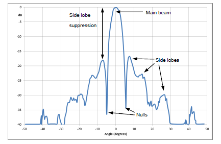
Usually antenna patterns are shown as plots in polar coordinates. This has the advantage that the radiation into all possible directions can quickly be visualized. In some occasions (i.e. for highly directive antennas) it can also be beneficial to plot the radiation pattern in Cartesian coordinates - because this reveals more details of the main beam and adjacent side lobes, see figure below.
From the radiation pattern the following additional parameters can be derived (see Figure below)
- The side lobe suppression (or side lobe level) is a measure of the relation between the main lobe and the highest side lobe.
- The half-power beamwidth (HPBW) is the angle between the two points in the main lobe of an antenna pattern that are down from the maximum by 3 dB. It is usually defined for both principal plane patterns.
- The front-to-back ratio specifies the level of radiation from the back of a directional antenna. It is the ratio of the peak gain in forward direction to the gain in the reverse (180°) direction. It is usually expressed in dB.
Reference : Antenna Basic - Rohde & Schwarz


No comments:
Post a Comment