Antenna Handbook

DIY Groundplane Antenna


Reliable communications in radio systems depends upon the over-all effectiveness of both the base station and mobile unit antennas. The radiation pattern of the transmitted signal is extremely important since it must be transmitted and received in densely populated areas as well as over long distances. If you are situated in the center of a town or a city, omnidirectional pattern is best suited for you. Omni- pattern is also the best choice when you do not know the exact direction or location of the station you are communicating with. Directive pattern is practical only if you know exactly which direction must the signal be beamed to, in order to maximize the transfer of RF energy. However, antennas with directive patterns are more complex in design and will be discussed later.
Generally, antennas for VHF bands are mounted as high off the ground as practical to overcome the limitations of the so called line-of-sight transmission and reception. An artificial ground must then be used since the antenna is well above the ground in this case. This is not a problem in automobiles since this artificial ground is provided by either the metal roof or body of the car. For tower installations however, some means must be provided to simulate this artificial ground. This is accomplished by the groundplane radials which are usually made of thin metal rods or tubes each cut to quarterwavelength long and mounted at the base of the antenna. The rods sometimes bend downward at an angle of about 45 degrees below the horizontal. This angle is important to maintain the correct impedance match of the system.


Construction 


First of all construct the antenna mount. It is made from a 1/8'' thick aluminum plate cut to 2'' x 6''. Drill a hole in the plate big enough for the SO-239 VHF connector to insert into (about 5/8'' or 15.8 mm). Drill the hole at the point about 1" away from one end (see Figure below).

Next drill four holes at the other end of the plate following Figure below for the proper dimensions. Make sure that the distance between one pair of holes perpendicular to the length of the metal sheet must be the same with the distance of both ends of the U-bolt that will be inserted into it.
Hole dimensions for the U-bolts

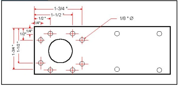
Next, drill eight holes (1/8" diameter) around the large hole following Figure below for the proper dimensions.
Hole dimensions for the radial elements around large hole.

Bend the aluminum plate down to a 90° angle (see Figure below). Follow the illustration for the exact point to bend. 

Bending The Aluminum mounting Plate

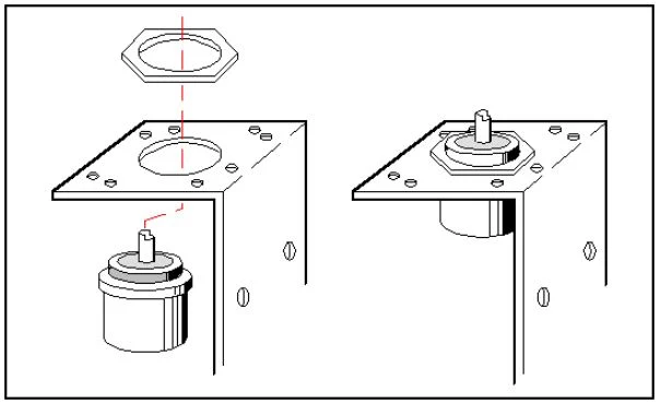
Insert the SO-239 VHF connector facing downwards into the mounting plate and fix it permanently with its nut (see Figure below). Discard the grounding ring/lug.

Mounting the SO-239 into the plate.

Cut the brass rod to a length of 19" (48.26 cm) and insert one of its end into the center pin of the SO-239 connector (see Figure below). The brass rod may or may not fit into the center pin immediately, so you may need to file away a small portion at the end of the rod to reduce it to a smaller diameter.

Preparing one end of the brass rod to fit inside the SO-239


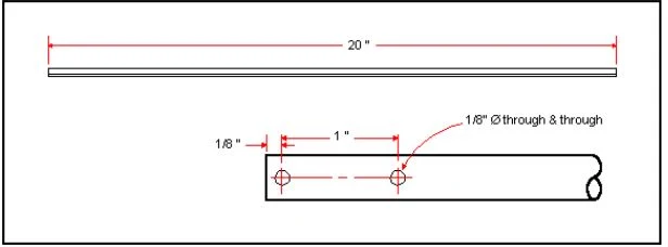
Cut four aluminum tubes to a length of 20" each and drill two holes (1/8 " diameter) at one end (see Figure below). 

Bend the aluminum tubes to a 45 degree angle at the point 1 inch away for the end with two holes. The direction of the bend must be parallel with the axis of the drilled hole (see Figure below). 

Bending The Tubes

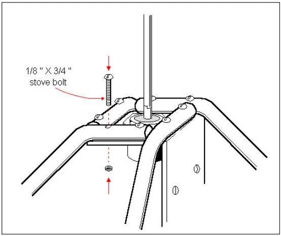
Mount the four aluminum tubes into the angled plate by bolting each element with 1/8" x 3/4" stove bolts (see Figure below). The stove bolts must be made of rust resistant material such as stainless steel, brass or GI. 

Mounting the tubes on the metal plate.

Finally , you can mount the antenna to the mast using the two U-bolts .

Mounting the antenna to the mast


ANTENNA FEED-POINT IMPEDANCE

An antenna simply hanging up in free space isn’t worth much; we need to get our energy from the transmitter up to the antenna. Of course, we can bend down one end of the an- tenna and bring it into the house—but, except for certain special types, this is not the best idea for several reasons. Some


energy may be wasted because of absorption by nearby objects. Also, the normal radiation pattern of the antenna may be some- what upset.
For these reasons, in most cases, some type of feeder line is used to get the energy from the transmitter to the antenna as Figure. At this point we need to consider another matter: the impedance of the antenna at the point where the feeder must connect. Fortunately, the theoretical input impedance of a half-wave antenna fed in the center is a value which can be matched by a feedline which, in turn, is of a handy impedance value for powering from the common ham transmitter. Such an arrangement is the basis of the first antenna we will consider.

DIY SWR Bridge , measure antenna SWR from 7 to 435 MHz with this cheap project

For over fifty years I have been matching my home-brew antennas to my radio, using makeshift field-strength-meters, lamps, pencils (arc), or finger (ouch). My solid-state amplifiers have complained about this treatment, however, forcing me to consider methods that really define the matching in terms of standing- wave ratio (swr). The effort resulted in a very simple device that measures swr to better than  1 : 1 in all the bands I am interested in, 7 to 435 MHz, it can be built in a few hours for less than few dollars. The basic method is a stripline-type directional coupler. The operating principle is that a properly terminated line parallel to, and coupled to, the transmission line will pick up energy traveling in one direction. The detected signal from this coupled line will represent either the forward or rcflected energy depending upon which end is terminated  Fig, 1 gives the schematic.

The Circuit


Swr values are determined from the forward and reflected peak- voltage outputs:

V(FWD)+V(RRFL) / V(FWD)-V(REFL)

The outputs can also be calibrated in terms of power. However* the output-voltage sensitivit>' of this type of directional coupler is directly proportional to frequency. As an example, using this particuhir device at 7 MHz, 100 Watts is required to detect an swr of hi, while at 146 MHz, less than 250 mW will make an equivalent measure- ment. This power/frequency relationship is a limitation.
The effect is in the right direction, how- ever. HF higher power is more likely available than at the VHF/UHF frequen- cies. Power-handling ability is also fre- quency related, and it is limited by the cou- pling -striptine terminalion resistors. Exam- ples arc about 4 W at 435 MH/, 35 W at 146 MHz, and 1 kW at 28 MHz, Total power dissipated at maximum power input is les3 than one Watt.
This project has been simplified by using a glue-down stripline technique that I have employed successfully in a number of previous projects. Striplines are cut from double-sided glass-epoxy PC board having the same dimensions that you would choose using the etched-PC board method. One side of the stripline is smeared with glue and pressed firmly against the common-base PC hoard. Changes can be made within minutes by lift- ing the glue-down stripline with a knife and replacing it with one having the altered dimensions. No dc connection is required between the glueline foils.
In this project, two striplines are glued together to effectively double the dielectric thickness. This results in a wider stripline for a given impedance, making fabrication and handling easier.
Matching the directional coupler-line impedance with that of the transmission line is a critical parameter, significant differences resulting in a self-generated swr error. Optimum strip! inc width was calculated using conventional stripline theory. Assuming a 50-Ohm Zo (line impedance), the calculations resulted in a 0.219-inch width when using two sandwiched 0.062-inch thick glass- epoxy PC strips having 1.5-ml foils (net J 18-inch dielectric). A dielectric constant of 4.5 was assumed for the glass-epoxy material. Tests indicate that the lloating center foils have no effect.
The pickup lines, glued to the top of the 50-Ohm conducting stripline, are 0. 125-inch wide, Although their calculated impedance is 69 Ohms, the termination resistance in this special configuration is about 60 Ohms. This resistance is experimentally pruned to null for zero output when the pickup is in a position to detect reflected energy and when the transmission line is terminated with a non-reflective load (50 Ohms). Pruning is accomplished easily using parallel 4-W resistors.
My assembly required four: two 150s, a 330, and a 2.2k-Ohm resistor. The resistor connections are with minimum lead lengths (approximately l/32nd inch). The assembly is reverse-connected in the transmission line to enable the pruning procedure for both pickup lines in an identical manner. Lack of fabricating symmetry will result in slightly different resistor values for the two pickup lines. A large output-readout dynamic range en- hances the usefulness of the device. As an example, only 1.2 V is indicated in the for- ward direction when used with my 7-MHz, 100-W transmitter. This means that to read a 1:1 swr, it is necessarv to detect a reflecitxl voltage of 0.057 V. 1 have found that selected lN34As will reliably meet this requirement. In a typical package often diodes from Radio Shack, over half of them had a back resis- tance of more than 10 Megohm (less than 1 uAat 10 V).
Using these selected diodes in the peak- detection circuit together with a high-im- pedance (10 Megohm) digital voltmeter permits reliable readings down to 0,05 V. The table in Fig. 2 shows input readout characteristics and the correction factors. The required readout sensitivity is a trade* off of how much power is available at a par- ticular frequency and the desired swr- mea- surement accuracy. The usual ham shack VOM- multimeter wilt be adequate for most applications.
Fabrication details are shown in the Fig. 3 layout, and the stripline cross-section draw* ing in Fig, 4. It is best to start by cementing the stripline sandwich and then finish trim- ming the edges to the required width. A file works fine, however — as does a sandpaper block, which will save dulling your file with the glass epoxy material.
The primary stripline width should be held toO.219 inch, ± 0.005 inches, I used calipers to size the striplines, but a ruler would be satisfactory if used with considerable care. Maintaining symmetry through the assembly is important. When mounting the BNC chas- sis connector, use a double nut so that it can be fastened in a position for minimum com- mon-return inductance.
Final alignment is simply pruning the pickup-line termination resistors in the man- ner mentioned earlier (multiple 1/4-W resis- tors). It is best to do this procedure at the highest frequency you intend to use the swr device— 1 used 435 MHz. One thing required is an accurate 50-Ohm termination. I used a fifty -fool section of RG-58/LJ terminated with two 100-Ohm, I /4-W resistors. The 7.5-dB cable loss reduces the estimated worst-case resistor reactance swr from a val- ue of 1.2 to L03
After pruning the lerminations of both pickup striplincs for minimum reflected indi- cation (less than 1 : 1 swr)» the device is ready to measure any swr of less than 10. The calibration results were made by terminating a short s^ection of RG-58/U with various values of 1/4 W resistors,
Inability to null the swr device may be the result of an error in the primary stripline impedance. This could be caused by a differ- ent gla&s-epoxy dielectric constant. Try alter- nate striplines differing in widths of about O.OiO inches.
Spurious responses In the transmitted source can cause a measurement error. As an example, a — 30 dB spurious signal is likely to result in a significant error when making a U swr measurement. Also* reflected signals from a reactive source will result in an error. This error will be particularly evident with large swr values.
Connectors also can be a suspect source of error. For example, I have used RG-59/U connectors {75 Ohm) for RG-8M cable (an RG-8 mini foam), and measurements indicate that they contribute to the swr.
How did my home-brew antennas mea- sure? The 435-MH2, 1 5-elemem antenna swr was 1.2, the 2m 5-element was 1 .4, the 2m J antenna was L4, and the 2Qm flat -top with a tuned antenna coupler ai the transmitter was
1.5. That makes sense, 1 spent more lime matching the UHF antenna.
In summation: You can match antennas adequately without an swr instrument, hut it's a lot easier if you have this simple gadget. Besides. it*s a good way to become acquaint- ed with directional couplers

DIY Field Strength Meter


The Circuit 


The circuit in Figure 1 shows how simple the FSM is to build. RF is coupled to Dl and D2, which are configured as a voltage doubler. The developed voltage is seen across the resistors RI and R2. R2 is the sensitivity control. Simple? You bet. So let's get started.

The most expensive part of the whole project is the meter movement. I got mine from Delia Electronics in Atlanta a few years back. Any value of meter from 50 uA(mu ampere) to 1 mA will work. The diodes Dl and D2 are general purpose germanium point contact diodes, 1 N34As or 1 N60s would be just fine, C 1 and C2 are 50-volt ceramic disc capacitors, I got mine in a grab bag at a hamfest Rl is l A watt and R2 is a 10k ohm pot from my junk box. I used a 2" x 3* x 1 1/2 inch plastic box from whereabouts unknown. The size of the box will be determined by the size of the meter that you use.

I mounted all the components on a small piece of perf board, then mounted the perf- board to the three solder lugs on the potentiometer R2. Next, mount the potentiometer in the hole cut for it in the box. Then connect the binding post to C 1 with a small length of hookup wire and connect the meter to the board. That's about all there is to it. Use your imagination to work out your own component mounting schemes. A word of caution: Don't forget to heat-sink the diodes' leads during soldering. Excessive heat can ruin them.

If you want to go to the extra trouble of making a printed circuit board, go ahead. Personally, I thought it was too much trouble for this particular project.

Testing the Meter

Testing is as simple as building the FSM. Just connect a short piece of stiff wire to the binding post and rotate the sensitivity control as you apply a signal to your antenna. It is a good idea to always start with the control all the way to the left to keep the needle from slamming into the stops, While the FSM only gives an indication of relative field strength, it will allow you to check for front-to-back ratio of beam antennas and to make a comparative analysis of different antennas. Get back into building and have fun

source : 73 Amateur Radio

How to pick up good Antenna TV or most for Antennas in General ?


There are many brands of antennas on the market, all of them promise good quality. This makes us need to determine what parameters help us to choose the right antenna, recommended according to the parameters of a good antenna

Impedance 

Pick 75 Ohm input Antenna ,  meaning , the input Antenna matched with Coaxial 75 Ohm cable Impedance  for TV , as Theory this will make the TV signal transmit/receive  ideally100 % without reflected.


Range

Scientific fact: The Earth is round. (Sorry, flat-earthers.) The curvature of the Earth will block most over-the-air broadcast signals at roughly 70 miles. According to the current laws of physics, it is generally impossible to deliver the 100 and 150-mile range claims some antenna manufacturers boast.

Gain

Indicates how well the antenna focuses energy from a particular direction, in comparison with a standard reference antenna (an antenna with known performance, used to calibrate other or developing antenna technologies). The gain number specified on an antenna is the value in the direction of maximum reception intensity. Example Antenna Gain 6 dB, 9 dB, 14 dB, 18 dB. the greater the antenna gain (in dB) the better the reception

What this means is that the distance measured for an antenna's reception capacity is based on the hypothetical instance where the broadcast transmitters you're trying to receive signals from all line up like points on a single straight line. Also, it is relevant to note that "gain" in this usage doesn't take into account possible dips in reception from what is called "impedance mismatch". In practice, the antenna's performance can be faulty if its impedance is different from that of the cable connected to it.


Model

Antenna model consist of by range criteria  Short Range/Medium Range/Long Range, by location installed Indoor/Outdoor/Attic Antenna ,  by frequency working UHF and UHF/VHF Antenna  and by Style , Wireless , Unidirectional (Directional)  and Multidirectional (Omnidirectional) Antenna

A Short-range digital TV antennas are engineered for distances within 50 miles of the broadcast towers. Their shorter range means they are very powerful and will consistently pick up your local signals.

A Medium-range TV antennas are engineered for distances within 60 miles of the broadcast towers. These high-performance digital antennas can be placed on a tabletop or a wall. For optimal performance and to minimize interference from electronic devices in the home, place the antenna near a window or on a wall facing the broadcast towers. Outdoor HD antennas will perform best when installed in your attic, or preferably on a rooftop or fascia.

A Long-range HD antennas reach further than most other outdoor TV antennas and minimize interference from obstacles such as trees or heavy foliage, providing you with the best possible reception in every scenario.

Indoor Antenna ,  indoor TV antennas are designed with timeless features to blend into sophisticated spaces. These indoor antennas can be painted to match your wall, furniture, or accent color for a custom fit.

Outdoor TV Antennas , Perfect for suburban and rural areas, outdoor TV antennas are the best option overall for receiving long-range signals when installed on a roof or fascia, providing the best line-of-sight to the broadcast towers.

Attic TV Antennas, Installing your antenna in an attic allows you to conceal your antenna when an outdoor antenna is not possible. Our attic TV antennas provide powerful, long-range performance for consistent, reliable reception in the city and in rural areas.

UHF Antennas, UHF HDTV antennas have the power and efficiency normally found in antennas up to 10 times their size.  TV antenna designs are engineered to receive consistent high-gain across the entire UHF TV spectrum. UHF signals are broadcast on channels 14 to 69 and have a higher noise level and greater attenuation, so  high-gain digital antennas are often required.

UHF/VHF Antennas, Over-the-air channels are divided into two bands, UHF and VHF.  High-VHF signals are broadcast on channels 7 to 13 and UHF signals are broadcast on channels 14 to 69. UHF/VHF HDTV antennas represent a breakthrough in long-range performance. They are engineered to be smaller and more powerful across today's DTV spectrum, with dedicated UHF and VHF multi-directional elements that deliver range and reception in less-than-ideal locations


  • If your location near Trasmitter locator tower and have Strong TV Signals, pick these Antennas

  •  If your location have Moderate TV Signals , Pick Up these Antennas


  • If your location have Weak TV Signals , Pick Up these Antennas


Filter

Some Antenna products , included this filter, the main function is to Blocks 4G/5G LTE cellphone and transmitter frequencies that cause pixelation and reception disruption. 

 
How to Get the Best Reception Antenna ?

The actual receivable range may largely depend on your location and distance. Areas with large obstacles, such as terrain, high concrete buildings, trees, valleys or mountains will reduce the effective range.

Also keep away from the high power device that will make interference when you install the antenna.

Use Transmitter Locator Software or other software related, will allow you to view the TV transmitters in your area. Using this tool, you will see the radius patterns showing

For example Enter your City name or ZIP Code and Click “Go” or Click “Go To My Locations” for Get DTV Coverage  

Please note:

These predictions are based on a terrain-sensitive propagation model resembling but not identical to the propagation model used when calculating service and interference contours for licensed broadcast television stations. Actual signal strength may vary based on a variety of factors, including, but not limited to, building construction, neighboring buildings and trees, weather, and specific reception hardware. Your signal strength may be significantly lower in extremely hilly areas. Click on a callsign for details about that station's Incentive Auction repacking plans.


Antenna Range False Claim

Antenna products in market claims have the receive signal  more than 100, 150, 200 miles, this is not true. We here to educate this false claims, there is no such antenna like that. 

The truth is TV antenna reception is influenced by the shape of the earth's curvature.

That's why TV stations need a lot of relay stations, to cover places that are far from TV tower stations such as rural areas, valleys behind mountains, and so on.

Curvature of Earth per mile

How large is the curvature of Earth, then? As we don't notice it in our everyday lives, it has to be relatively small. Most sources consider 8 inches per mile as the most accurate estimate. That means that for every mile between you and an object, the curvature will obstruct 8 inches of the object's height.

Scientific fact: The Earth is round. (Sorry, flat-earthers.) The curvature of the Earth will block most over-the-air broadcast signals at roughly 70 miles. According to the current laws of physics, it is generally impossible to deliver the 100 and 150-mile range claims some antenna manufacturers boast. While you may receive signals from farther away in absolutely ideal conditions (a home atop a hill whose broadcast towers are directly on top of another hill with a clear shot between the two and absolutely no obstacles) or you’re inclined to engineer a unique (and probably dangerously tall) setup, then consistent, reliable reception of anything over 70 miles away should not be expected. Range can also be impacted by factors such as location, obstructions in the terrain around you, other buildings, the location of transmitters on the broadcast tower, and other variables


The Channels You'll Receive

You may be thinking that watching TV with an antenna will bring you back to the old days of antennas when only a handful of stations were available. Today, most areas in the United States broadcast 50+ channels over the air. Locations like Los Angeles have as many as 175 channels. We’re talking about over-the-air broadcast television channels -which are transmitted in Full HD 1080p and with 5.1 surround sound- you receive for FREE once you have a TV antenna. In addition to your local NBC, CBS, ABC, CW, and FOX affiliates, you’ll also find a wide variety of specialty programming available on these stations. So much content is available over-the-air that we like to call it “the new basic cable”. Keep in mind, these are network and local channels. You won't receive any pay-TV stations via a TV antenna, ever. We’ve seen antennas claiming this possibility, but it is 100% false. You will not receive ESPN, CNN, or any other such channel with a TV antenna. Period. That said, there are many new streaming options becoming available all the time which combine broadcast TV content with packages available for purchase to watch sports channels, pay-TV subscriptions, and more, all from one streamlined platform.


The 4k TV Antenna

As of writing this, OTA television is not yet broadcast to the general public in 4K. However, that doesn’t stop unscrupulous antenna companies from claiming that (only) their antennas will allow you to watch broadcast TV in 4K. The truth is, once 4K broadcast television becomes available, any antenna will be able to receive it. What you, the TV-watcher, will need in order to view OTA television in 4K is a device which will be capable of decoding the transmissions your antenna receives so that you’re able to watch your shows in the new 4K standard. This can be a TV or a designated TV tuner, for example, a set-top box. We believe that our ClearStream™ HDTV Antennas will deliver the best, most reliable picture quality we’ve always been known for when that day comes, which is why we indicate on our packaging that all our antennas are “4K-Ready”. Until then, 4K-quality picture has become available through mediums such as Blu-Ray® and certain streaming services, but broadcast television viewers will need to wait until the new standard of television arrives on local airwaves in the near future, to view over-the-air television in 4K.

If you’re still unsure or just need guidance choosing the right antenna for your needs, we are here to serve as your beacons of light for all antenna myths you may be grappling with. Our Midwest-based Connection Crew is available 7 days a week to answer questions and help you achieve the best possible over-the-air TV-viewing experience. They’ll help you pick the right antenna for your location, troubleshoot installation, conduct a free home signal analysis, and more. They’re a passionate bunch of real antenna enthusiasts who will help you separate fact from fiction and find success with a TV antenna.


Reference :

http://www.Antennasdirect.com

http://www.amazon.com

https://www.fcc.gov/media/engineering/dtvmaps

https://www.omnicalculator.com/physics/earth-curvature#curvature-of-earth-per-mile