
Reliable communications in radio systems depends upon the over-all effectiveness of both the base station and mobile unit antennas. The radiation pattern of the transmitted signal is extremely important since it must be transmitted and received in densely populated areas as well as over long distances. If you are situated in the center of a town or a city, omnidirectional pattern is best suited for you. Omni- pattern is also the best choice when you do not know the exact direction or location of the station you are communicating with. Directive pattern is practical only if you know exactly which direction must the signal be beamed to, in order to maximize the transfer of RF energy. However, antennas with directive patterns are more complex in design and will be discussed later.
Generally, antennas for VHF bands are mounted as high off the ground as practical to overcome the limitations of the so called line-of-sight transmission and reception. An artificial ground must then be used since the antenna is well above the ground in this case. This is not a problem in automobiles since this artificial ground is provided by either the metal roof or body of the car. For tower installations however, some means must be provided to simulate this artificial ground. This is accomplished by the groundplane radials which are usually made of thin metal rods or tubes each cut to quarterwavelength long and mounted at the base of the antenna. The rods sometimes bend downward at an angle of about 45 degrees below the horizontal. This angle is important to maintain the correct impedance match of the system.

Construction
First of all construct the antenna mount. It is made from a 1/8'' thick aluminum
plate cut to 2'' x 6''. Drill a hole in the plate big enough for the SO-239 VHF
connector to insert into (about 5/8'' or 15.8 mm). Drill the hole at the point about
1" away from one end (see Figure below).

Next drill four holes at the other end of the plate following Figure below for the
proper dimensions. Make sure that the distance between one pair of holes
perpendicular to the length of the metal sheet must be the same with the
distance of both ends of the U-bolt that will be inserted into it.
 |
| Hole dimensions for the U-bolts |
Next, drill eight holes (1/8" diameter) around the large hole following Figure below for the proper dimensions.
 |
| Hole dimensions for the radial elements around large hole. |
Bend the aluminum plate down to a 90° angle (see Figure below). Follow the illustration for the exact point to bend.
 |
| Bending The Aluminum mounting Plate |
Insert the SO-239 VHF connector facing downwards into the mounting plate and fix it permanently with its nut (see Figure below). Discard the grounding ring/lug.
 |
| Mounting the SO-239 into the plate. Cut the brass rod to
a length of 19"
(48.26 cm) and
insert one of its end
into the center pin
of the SO-239
connector (see
Figure below). The
brass rod may or
may not fit into the
center pin
immediately, so you
may need to file
away a small
portion at the end
of the rod to reduce
it to a smaller
diameter.
|
 |
| Preparing one end of the brass rod to fit inside the SO-239 |

Bend the aluminum tubes to a 45 degree angle at the point 1 inch away for the
end with two holes. The direction of the bend must be parallel with the axis of
the drilled hole (see Figure below).
 |
| Bending The Tubes |
Mount the four aluminum tubes into the angled plate by bolting each element
with 1/8" x 3/4" stove bolts (see Figure below). The stove bolts must be made of
rust resistant material such as stainless steel, brass or GI.
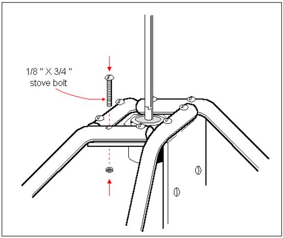 |
| Mounting the tubes on the metal plate. |
Finally , you can mount the antenna to the mast using the two U-bolts .
 |
| Mounting the antenna to the mast source : Practical Antenna Design VHF-UHF |
No comments:
Post a Comment