Antenna Handbook

The Noise Bridge

There is another instrument that you may use for resonance tests. It is known as a noise bridge. It is connected between your receiver and the feed line to the antenna. Your antenna will be purely resistive at resonance, so the null in the noise from the bridge will be the deepest at the frequency of antenna resonance.

The reactance controls on the noise bridge will be at zero when this null occurs. The bridge will provide a resistance reading when fully nulled, and this will indicate not only antenna resonance, but allow you to read the feed-point impedance (resistive) of the antenna. In order for this instrument to be accurate, you must use an electrical half wavelength of coaxial feeder between the antenna and the bridge.

The instrument generates white noise, and this is heard in the receiver output (speaker of phones). The bridge controls are adjusted for minimum noise to indicate antenna resonance. You will need to tune your receiver to various frequencies in the ham band of interest in order to locate the resonant frequency of the antenna.

The noise bridge is readjusted for a null at each of these frequencies until you find a frequency that yields a deep null with the reactance controls at zero. This may seem complicated now, but if you study the operating booklet for your noise bridge, things will fall into place easily.

source : Novice Antenna Notebook by DeMaw, Doug

Finding the Correct Dipole Length

We have discussed the standard formula for cutting a dipole to length [L = 468/f(MHz)]. First, you may wonder why 468 is used instead of the free-space factor of 492 for a half wavelength. This is a good question: If our dipole was in free space and with no feed line, the length would be greater than that obtained from the 468 factor. The end effects of the insulators and guy lines, plus antenna proximity to trees, the earth and other influences, causes the antenna to have stray-capacitance effects that tune it lower in frequency. 

You may think of the dipole as an inductance, and stray capacit- ance appears in parallel with it, just like in other tuned circuits. These effects are compensated for by changing the length factor from 492 to 468.

Let's assume that you have cut your dipole wires in accordance with 468/f, as discussed earlier. How can you be certain that this is the correct length (antenna installed) for your chosen frequency of operation, say, 3.7 MHz?

 First, you need to know that the lowest SWR occurs at the resonant frequency of your antenna. It may not be the ideal 1:1 ratio we seek. Rather, it may be 1.5:1 or even 2.3:1. If the SWR is high at the reson- ant frequency of the dipole, you will know that the feed line is not matched to the antenna feed point. The SWR will rise either side of the resonant frequency as you change the operatYou will need an SWR indicator or bridge, as they are called, in order to check your antenna resonance and SWR. 

The SWR indicator must be designed for the impedance of your feed line, such as a 50-ohm bridge for 50-ohm coaxial line. The SWR instrument is installed between your transmitter and the feed line. 

Next, check across the amateur band for which your dipole is cut, observing the SWR reading every 25 kHz or so. Note the frequency at which you obtain the lowest SWR reading (minimum reflected power). 

This will occur at the resonant frequency of the antenna. If the lowest SWR occurs lower in the band than your design calls for, remove small amounts of wire from the ends of the dipole until the lowest SWR is noted at the preferred antenna resonance point. If the lowest SWR reading is observed higher than your chosen frequency, you must add a small amount of wire to the ends of the dipole. Continue this process until the lowest SWR occurs at the chosen operating frequency.

You may use a dip meter for checking the resonance of your antenna. You may do this by connecting a three- or four-turn small coil between the shield braid and inner conductor of your coaxial cable (antenna erected, and feed line attached). A solid-state or tube type of dipper may be used. Insert the dip-meter coil into the small coupling coil on the feeder. Adjust the dipper through its range and locate the frequency at which a deep dip is noted on the meter. Listen to the dip- meter operating frequency by means of your receiver, and note the frequency. Adjust the dipole length until the dip meter indicates resonance at your preferred operating frequency.

We will discuss methods for mismatch correction, later in in this notebook. A minor mismatch (1.5:1 SWR or less) is not of concern to us for routine operation, provided the trans- mitter is designed to deliver normal output power at low values of SWR.

source : Novice Antenna Notebook by DeMaw, Doug

The Folded Dipole

A folded dipole has two conductors in parallel, as you can see in Fig-3. This antenna has a high feed impedance (300 ohms). You may use a 4:1 balun transformer (see later chapter on baluns) to convert the 300-ohm balanced line to 75-ohm coaxial cable. A folded dipole may be used in the same manner as the single-wire dipoles in article Building and using Dipole Antennas .

The advantage of a folded dipole is that it provides slightuiy greater bandwidth between the 2:1 SWR points (most modern transmitters have a protective circuit that reduces the power as the SWR increases) than is characteristic of a single-wire dipole. For example, an 80-meter single wire dipole might have an SWR bandwidth (2:1 SWR boundries) of 75 kHz. 

A folded dipole for the same frequency may have an SWR bandwidth of 100 kHz. Apart from this consideration there is nothing to be gained from choosing a folded dipole. I have included it in this chapter for your enlightenment.

Example of a folded-dipole antenna. The characteristic feed impedance is 300 ohms. A 4:1 balun transformer converts the balanced feeder to a 75-ohm unbalanced line (RG-11 cable). This antenna may be fabricated from 300-ohm TV ribbon line or 450-ohm ladder line. The outer ends of the dipole are shorted as shown by the dots near the end insulators.


source : Novice Antenna Notebook
               by DeMaw, Doug

BUILDING AND USING DIPOLE ANTENNAS

Perhaps the most common amateur antenna in use today is the dipole. It is inexpensive to construct, and it provides good results for local and DX communications if it is erected high above ground. 

A dipole antenna is a 1/2-wavelength conductor that is fed at the electrical center. Gain types of directional antennas, such as the log periodic dipole array consists of a group of dipoles. In other words we can combine a number of dipoles to form a wideband log-periodic beam antenna.

A single dipole antenna has no gain, but it does exhibit a bidirectional radiation pattern if it is a half wavelength or greater above ground, and if it is erected for horizontal polarization (parallel to the earth). The radiation pattern for this type of dipole resembles a figure below. Maximum radiation is off the broad side of the antenna.

We learned that a dipole antenna loses its direct-ional characteristics when it is placed close to ground (less than approximately 0.5 wavelength). The resultant radiation pattern for a dipole that is, say, 1/20 wavelength above ground (e.g., 53 feet for 3.7 MHz), is pretty much circular. In other words, the signal is radiated almost equally in all directions. Also, the radiation angle will be very high, which is not ideal for long-distance communications.

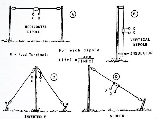
Dipoles may be erected horizontally or vertically. They may also be configured as inverted Vs. This is a popular format because only one tall support pole or tower is needed. The center of the dipole is held aloft by the tall supporting structure, and the halves of the dipole droop toward ground at approximately 45 degrees. You may also use your dipole as a sloper (sloping dipole). In this example , see figure 1, we tie one end of the dipole to a tall mast or tower and slope the entire antenna toward ground at approximately 45 degrees. The lower end of the antenna (as with an inverted V) is just a few feet above ground-in a typical case where the tower or mast height is 50-60 feet.

Radiation angles and patterns vary in accordance with the manner in which we erect our dipole antennas. A vertical dipole, for example, has an omnidirectional radiation pattern, and it exhibits a relatively low radiation angle. Sloping dipoles and inverted Vs with an enclosed angle of 90 to 100 degrees will also radiate a vertically polarized signal. The sloper will have a unidirectional pattern off the slope of the antenna (directivity rather than gain) if it is supported by a metal Mast or tower: 
the metal support device acts somewhat as a reflector, If the sloper is supported on a wooden pole, the radiation pattern will be omnidirectional. 

Inverted-V antennas also have an omnidirectional pattern if they are erected in a symmetrical manner, respective to the tower and placement of the antenna legs.
Fig 1. Examples of how half-wave dipoles may be erected. A figure-8 radiation pattern results from the arrangement at A, Antenna B has an omni- directional pattern and vertical polarization. Antennas C and D also have vertical polarization and omnidirectional patterns assuming the enclosed angle at C is 90-100 degrees, and when antenna D slopes approximately 45 degrees toward ground from a nonconductive mast


The feed impedance of the antennas in above figure, ranges from approximately 35 to 75 ohms. The actual value is dependent upon the height above ground, and in the case of antennas C and D, the angle of the wires respective to mast. 

For most amateur operation you may use 50-ohm coaxial cable to feed these antennas, provided the feeder length is 100 feet or less. The losses from the moderate SWR (standing-wave ratio) at high frequency will be minimal if quality cable is used, such as RG-8 line. 

The antennas in Figure 1 are for single band use when coaxial feed line is employed. Multiband operation is possible if you use tuned feed line and a Transmatch.

See Figure 2  for this hookup. If you wish to take advantage of the multiband concept with your dipole, you should cut it to length for the lowest operating frequency of interest. By way of illustration, your dipole should be dimensioned for 80 meters if you plan to use it from 80 through 10 meters. 

The formula for half-wave dipoles is given in Fig 1. Thus, a dipole for 3.7 MHz will be roughly 126 feet, 6 inches long, overall. I said "approximately" because the final length is determined by the installation. Height above ground and nearby conductive objects will affect the initial 468/f(MHz) dimension somewhat. You may need to cut a few inches of wire off the ends of the dipole halves in order to obtain minimum SWR An SWR bridge is used when making the final adjustments.

Fig 2- Example of a multiband dipole that has balanced, tuned feeders. The feed-line impedance is not critical provided it is between 300 and 600 ohms. TV ribbon line may be used, or the line may be 450-ohm ladder type. Homemade open-wire feed line is the best in the interest of minimum RF power loss. The Transmatch (transmitter to feed-line matcher) should be designed for balanced feed line. If not, a 4:1 balun transformer must be used between the balanced feeder and the Transmatch. The SWR is adjust- ed for a 1:1 condition while observing the SWR meter (minimum reflected power) for each frequency of operation,

source : Novice Antenna Notebook
               by DeMaw, Doug


Your's Antenna Personality

Some newcomers are confused about the proper type of conductors to use for antennas. I have been asked, for example, "Can I use wire that has plastic insulation?" Another common inquiry is, "What is the best wire gauge or diameter for my dipole?"
Still another question is, "Which is best? Stranded or solid wire?"

These are good questions, and I fault no one for asking them. Consider the first question. After all, insulation is used to confine ac and dc voltage in circuit wiring. This prevents unwanted short circuits, and the insulation protects us from electrical shock. Therefore, it is reasonable for a beginner to assume that RF (radio-frequency) energy cannot be radiated through the insulation. 

Actually, this insulating layer has little effect on the radiation of an antenna. It will, however, slow down the passage of RF energy at the higher frequencies, such as VHF and UHF signals. It introduces what is known as a propagation or velocity factor. When this happens we must shorten the wire slightly to compensate for the velocity factor. At HF (high frequency), the effects of insulation are so minor that we can ignore them.

The thinner the insulating material on wire, the better. This is because insulation adds to the weight of the wire, and we may have a problem supporting an insulated-wire antenna because of its weight. It may sag or cause the support masts to bow or break. It is for this reason that most amateurs use bare stranded no. 14 copper wire for antennas. Others prefer enameled single-conductor wire. The insulation is beneficial because it prevents the copper conductor from becom- ing corroded in the presence of contaminants in the air. This enameled wire will, however, break more readily from flexing in the wind than will stranded copper wire of the same gauge.
 

Furthermore, soft-drawn single-conductor copper wire will stretch with time, and this will change the resonant frequency of the antenna (move it lower in frequency). For this reason you should make certain that you purchase hard-drawn copper wire.

A stronger type of wire is available. It is known as Copper- weld (TM), to signify that it has a steel core with a copper coating. It is difficult to work with because it is quite springy and hard to manage. It is very rugged wire, and it should stay aloft for years. You should avoid kinking it during handling. Avoid sharp bends in the wire also. Kinking and radical bending ruptures the copper covering, and this allows moisture and pollutants to reach the steel core. 

This will, in time, cause the wire to break.
Wire gauges 12 and 14 are the most popular among amateurs. These sizes offer good strength, cross-sectional area and acceptable weight. This does not mean that you can't use other gauges of wire. I have used 130-foot spans of no. 26 enameled wire for "invisible" end-fed antennas. 

The systems worked fine, but needed to be replaced frequently from breakage. I have also used no. 8 solid copper wire (heavy!) for dipoles and end-fed antennas. The larger the wire diameter the lower the antenna Q (quality factor). 

This won't degrade the antenna performance. Rather, the lower the Q the greater the antenna bandwidth. For example, an 80-meter dipole made from no. 18 wire might have an SWR bandwidth (frequency between the 2:1 SWR points) of, say, 50 kHz. The same antenna, if made from no. 10 copper wire, might have a 75-kHz SWR bandwidth.

Vinyl-covered electrical house wiring is entirely suitable for building antennas, but it is quite heavy. I do not use it for long horizontal spans. I find that it is OK for use in inverted-V and similar antennas that have drooping elements. The vinyl covering adds strength, and this can be helpful if you live in an area where high wind and ice storms are frequent.

Many types of commonly available wire may be used for building antennas. For example, I have made a variety of antennas from no. 18 insulated speaker wire. I split the two conductors, which can be pulled apart easily.

This gives me twice as many feet of wire per roll than before the separation is done. Electric fence wire is used by a number of amateurs. It is very inexpensive, and comes in no. 18 Copperweld or aluminum materials, Checkwith your area farm-supply store, or Sears, for this and other suitable wire.

Some beam antennas and verticals can be made from common items that may be found locally. Commercial antennas of this kind are fashioned from aluminum tubing of a specified tensile strength and hardness. This material is not only hard to find, but it is expensive. You may prefer to make your small beam antenna or vertical from thin-wall electrical conduit. The antenna will be heavier than if aluminum were used, and it will eventually become rusty unless you paint the metal.

I have made a number of vertical antennas from copper tubins that I purchased at a plumbing-supply store. The 1/2- or 3/4 inch copper tubing may be supported on standoff insulatore that are attached to a wooden mast. I have also employed thin wall electrical conduit for the conductor of a vertical antenne Aluminum downspout (gutter) sections may be joined to form a guyed vertical antenna for 40 meters and higher. I know a ham operator who has access to used irrigation pipe. 

He made a lovely guyed, 80-meter vertical from this stock.
It is important that you be innovative when selecting material for your homemade antennas. Not only will you save money, you will be able to acquire the components quickly. Although iron is not as ideal a conductor as aluminum or copper, it will perform well for medium- and high-frequency operation.

source : Novis Antenna Notebook by Doug DeMaw, W1FB