Antenna Handbook

Stepper Motor Generator


Any stepper motor can be used as a generator. In contrast to other generators, a stepper motor produces a large induced voltage even at low rotational speeds. The type used here, with a DC resistance of 2x60 Q per winding, can generate more than 20 V when turned by hand, without any gearing. The circuit diagram for a 'hand-cranked torch' shows how you can use a stepper motor as a generator.

A supplementary circuit stores the energy. Two bridge rectifiers, each made up of four 1N4148 diodes, charge the 4700-jL/F capacitor. The super-bright (white) LED is driven either via a 390-Q resistor (Power Light), or via 22 kQ in series with 390 Q. In the latter case, the LED is not as bright, but it stays on longer. You must restrain yourself when cranking the dynamo, since in the 'bright' setting it is possible to exceed the rated LED current of 20 mA, while in the 'long' setting it is possible to exceed the rated capacitor voltage of 25 V If necessary, adjust the value of the LED series resistor.

The lamp is bright enough for reading in complete darkness. The stepper motor generator is thus ideal for spies, thieves and children who want to read under the bedcovers. You could also keep it handy in your hobby room, in case of a short circuit

0-44 dB RF Attenuator

Anyone who has to reduce the amplitudes of RF signals in a controlled manner needs an attenuator. Linearly adjustable attenuation networks using special PIN diodes are available for this, but they require quite intricate control circuitry.

A simpler solution is to use an integrated attenuator that can be switched in steps. The RF 2420 is an IC built using gallium- arsenide (GaAs) technology, which works in the frequency range between 1 MHz and 950 MHz. It can thus be used as an attenuator for cable television signals, for example. The attenuation can be set between 0 and 44 dB in 2-dB steps. An insertion loss of 4 dB must also be taken into account. This base attenuation can be measured in the 0-dB setting, and it forms the reference point for switchable attenuation networks that provide 2, 4, 8, 10 and 20 dB of attenuation. These are all controlled by a set of 5 TTL inputs. The control signals must have Low levels below 0.3 V and High levels of at least +2.5 V The RF 2420 works with a supply voltage between + 3 V and + 6 V, with a typical current consumption of 4 mA. A power-down mode, in which the current consumption drops to 0.8 mA, can be activated by removing power from the bussed V DD - pins.

The sample circuit diagram for the RF 2420 shows that the only external components that are needed are decoupling capacitors. The coupling capacitors at the input and output determine the lower operating frequency


10 to 1000 Oscillator


Nowadays, it is no longer necessary to use discrete components to build oscillators. Instead, many manufacturers provide ready-made voltage-controlled oscillator (VCO) ICs that need only a few frequency-determining external components. One example is the RF Micro Devices RF2506. This IC operates with a supply voltage between 2.7 and 3.6 V (3.3 V nominal) and provides a low-noise oscillator transistor with integrated DC bias setting. In addition, it has an isolating buffer amplifier that strongly reduces the effects of load variations (load pulling) on the oscillator. If a voltage less than 0.7 V is applied to the power-down input (pin 8), the oscillator is shut down and the current consumption drops from 9 mA to less than 1 uA/A. The VCO is enabled when the voltage on pin 8 is at least +3.0 V

Connecting the feedback capacitors CI and C2 to pins 3 (FDBK) and 4 (VTUNE) transforms the internal transistor into a Colpitts oscillator. A resonator is also needed; here this consists of C4 and LI, and it is coupled via C3. Keep the Q factor of the coil as high as possible (by using an air-core coil, for example), to ensure a low level of phase noise. Since most applications require a tuneable oscillator, the varicap diode Dl (BBY40, BBY51, BB804 etc) can be used to adjust the resonant frequency. The tuning voltage is applied via a high resistance. The value of the tuning voltage naturally depends on the desired frequency range and the variable-capacitance diode (Dl) that is used. The table RF2506 shows a number of suggestions V o for selecting the frequency-determining components.


If the frequency range is narrow, FDE a parallel-resonant circuit should vtui be connected between the output pin and +V CC , to form the collector load for the output transistor. This can be built using the same components as the oscillator resonator. With a broadband VCO, use a HF choke instead, with a value of a few microhenries to a few nanohenries, depending on the frequency band. In this case C6 is not needed. The output level of this circuit is -3 dBm with an LC load and -7 dBm with a choke load.

The table that accompanies the schematic diagram provides

rough indications of component values for various frequencies. It is intended to provide a starting point for experimentation. The coupling between the variable-capacitance diode and C5 determines the tuning range of the VCO. The manufacturer maintains an Internet site at www.rfmd.com, where you can find more information about this interesting oscillator IC


source : Elektor Circuit Collections 2000-2014

Simple RF Detector for 2 m

This simple circuit helps you sniff out RF radiation leaking from your transmitter, improper joints, a broken cable or equipment with poor RF shielding. The tester is designed for the 2-m amateur radio band (144-146 MHz in Europe).

The instrument has a 4-step LED readout and an audible alarm for high radiation voltages. The RF signal is picked up by an antenna and made to resonate by CI -LI. After rectifying by diode Dl, the signal is fed to a two-transistor highgain Darlington amplifier, T2T3. Assuming that a 10-inch telescopic antenna is used, the RF level scale set up for the LEDs is as follows:


When all LEDs light, the (optional) UM66 sound/melody generator chip (IC1) is also actuated and supplies an audible alarm. By changing the values of zener diodes D2, D4, D6 and D8, the step size

and span of the instrument may be changed as required. For operation in other ham or PMR bands, simply change the resonant network CI -LI.

As an example, a 5-watt handheld transceiver fitted with a half-wave telescopic antenna (G = 3.5 dBd), will produce an ERP (effective radiated power) of almost 10 watts and an e.m.f. of more than 8 volts close to your head.


Inductor LI consists of 2.5 turns of 20 SWG (approx. 1 mm dia) enamelled copper wire. The inside diameter is about 7 mm and no core is used. The associated trimmer capacitor CI is tuned for the highest number of LEDs to light at a relatively low fleldstrength put up by a 2-m transceiver transmitting at 145 MHz.

The tester is powered by a 9-V battery and draws about 15 mA when all LEDs are on. It should be enclosed in a metal case.

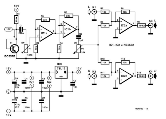
Noise Injector


This Circuit is primarily intended to be used by persons who want to experiment with audio. For example, you can determine whether your own audible threshold for noise is different with and without music, or whether a particular CD sounds better with a little bit of noise. However, since this circuit produces white noise, it can also be used for test measurements, such as comparing the sounds of different loudspeakers, measuring filter characteristics and so on. The measured characteristics, as shown in Figure 2, show a nearly flat amplitude distribution (averaged over 64 measurements). The effective value of the noise signal at the output is around 100 mV maximum (with both potentiometers set to maximum), measured over the frequency range of 22 Hz to 22 kHz.

The noise is generated by reverse-biasing the base-emitter junction of a PNP transistor (BC557B) so that it zeners. In our prototype, the voltage across Tl was approximately 10 V. PI is used to set the level of the generated noise so that it is just audible, following which the output level can be adjusted using the logarithmic potentiometer P2. For making measurements, PI can also be simply set to its maximum position. The noise is amplified by two opamp stages. Depending on the transistor manufacturer, or the type of transistor if you use a different type, the level of the generated noise can vary significantly. Using two amplification stages in series provides more options and considerably more bandwidth, and you can implement various filter characteristics around ICla and IClb according to your own taste. The gain of the two stages has been kept equal to ensure the maximum possible bandwidth. The amplified signal is then passed to a simple summing amplifier (IC2). We have used a stereo arrangement, in which both channels receive the same noise signal. If you want to expand on the design, you can provide each channel with its own noise generator. In this case, you will have to use a dual potentiometer for P2.

The well-known NE5532 is used for the amplifiers, but any other good dual opamp would also be satisfactory. The opamps are fed from a standard, symmetrical ±15-V supply. In order to suppress possible positive feedback via the power supply, and to reduce the effects of power supply noise (since the opamps are non-inverting), the supply for the noise diode circuit (Rl and Tl) is separately stabilised by IC3 (7812) and extra filtering for the ± 15-V supply is provided by C8 and C9. IC3 must be located as close as possible to Rl, Tl and IC1. The coupling capacitors CI and C2 are necessary to prevent the DC component of the noise signal from appearing at the outputs.

The table lists some measured characteristics of the circuit, for a bandwidth B of 22 Hz to 22 kHz and a reference level of 2V eff .