Antenna Handbook

Opentherm Monitor Circuit


If you say that the term ‘Opentherm’ is unfamiliar to you, then this will not surprise us the least. Opentherm is a protocol, which can control central heating boilers and hot water systems digitally. ‘Open’ indicates that it is not specific to a single brand. Anyone can, in principle, make use of this protocol, provided you are prepared to hand over several thousand pounds for ‘membership’ and are prepared to keep the information secret (talk about ‘open’…). As a consequence we unfortunately do not know a great
deal about it, but we do have a few technically interesting pieces of information we would like to share with you.

The connection between the master device (usually the room thermostat) and the slave (typically the central heating boiler) consists of two wires, which permits the use of existing cabling. Via this cable the boiler powers the thermostat with DC. In order to prevent wiring errors, the thermostat is fitted with a bridge rectifier, allowing the conductors (positive and negative) to be reversed. The installer cannot make any mistakes here. The master places on this connection a digital signal. Every second, 32-bits are transmitted in Manchester-code and after about 0.2 seconds the slave responds with the return message. Every bit lasts 1 ms,
and a message consists of:

1 Start bit (logical zero)
1 Parity bit
3 Message type
4 Spare
8 Data ID
16 Data
1 Stop bit (logic zero)


From the electrical perspective, an interesting solution has been selected. The boiler sources current, a logic Low is a current between 5 and 9 mA, a logic High a current between 17 and 23 mA. This way the thermostat is always powered. In the opposite direction, the thermostat signals by pulling down the open circuit boiler voltage of 24 V to a voltage less than 9 V (logic Low) or between 15 and 18 V for a logic High. 

So, at the risk of over-emphasising: the boiler provides information by modulating the current, and the thermostat by changing the voltage. All this can easily be observed on an oscilloscope. In order to follow the activities, we have designed a circuit that does not unduly influence the operation, although it causes an unavoidably small voltage drop of course. The boiler is connected to K1; the polarity is of no consequence  because the connector is followed by a bridge rectifier (D1- D4). The thermostat is connected to K2. R4 and IC1a look if the current corresponds with a logic ‘Low’ or a ‘High’ and signal this, electrically isolated, to the DCD of the serial input of your computer. The voltage of the connection is
monitored by R6, R7 and IC1b and copied to DSR. An oscilloscope connected to these points easily shows you the messages going back and forth. It is likely that the current channel shows both messages. When the voltage on the wires changes, there is also an inevitable change in current because the thermostat is a capacitive load. The circuit is powered from the RTS and DSR hand
shaking lines. They have to be made logic Low first, of course. Naturally, it is also possible to connect a power supply of around 10 to 12 V behind the diodes. Those who are keen can write a program to read the serial inputs and decode the Manchester-code to data. Certain information, such as room and boiler temperature can easily be found. Unfortunately we do not have any more information and neither do we have a program. Every now and then there is something to be found in the Internet, so it may be sensible to keep an eye this.

source : Elektor Circuit Collections 2000-2014

Three Component Oscillator


At first glance, this circuit appears to be just a primitive microphone amplifier. Why then is the title of this article
‘Three-component Oscillator’? The answer is very simple:
the microphone is not intended to pick up speech; instead, it is placed so close to the loudspeaker that massive positive feedback occurs. Here we intentionally exploit an effect that is assiduously avoided in public-address systems — the positive feedback results in a terribly loud whistle. The loudspeaker is connected directly to the 12-V supply voltage and the power transistor, so it must be able to handle a power of at least 1.5 W, and it should have an impedance of 8 to 16 . An outstanding candidate can be cannibalised
from an old television set or discarded speaker box. The microphone should be a carbon-powder type from an old-fashioned telephone handset. If you place a switch in series with the power supply, this sound generator can also be used as an effective doorbell or siren. Surprisingly enough, the circuit can also be used as a simple microphone amplifier — hardly hi-fi, of course, but still usable.

source : P. Lay - Elektor Circuit Collections 

2.5-GHz Signal Source


More and more communications systems are operating in the 2.4-GHz ISM (Industrial, Scientific and Medical) band, including Blue
tooth, various WLAN (Wireless Local Area Network) and Home-RF systems. A simple test oscillator for the frequency band between 2.4 GHz and 2.5 GHz can prove useful in testing receivers. Such an oscillator is available from Maxim (www.maxim-ic.com) as a single IC. The MAX2750 covers the frequency range between 2,4 GHz and 2.5 GHz using in internal LC network that can be tuned using a varactor diode that is also built into the IC. An output buffer delivers a level of –3 dBm into 50 .
This component is housed in an 8-pin µMAX package. The circuit is powered from a 9-V battery. The BC238C transistor stabilises the battery voltage at around 4 V. Although the MAX2750 can work with supply voltages
between +2.7 V and +5.5 V, the frequency stability of the free-running oscillator is better with a stabilised supply voltage. All connections to the IC are decoupled using 220pF capacitors, which must be located as close as possible to the IC pins. The tuning voltage at pin 2, TUNE, may lie between +0.4 V and +2.4 V, which provides a tuning range between 2.4 GHz and 2.5 GHz. If it is desired to switch off the oscillator, this can be done by connecting the Shutdown input (SHDN) to earth potential. When the IC is shut down, its current consumption drops to around 1 µA. Here the shutdown input is connected to the Vcc potential by a pull-up resistor, so that the oscillator runs. The –3 dB output level can be reduced using the indicated pi attenuator. A number of resistance values for this attenuator are shown in the table.

source: Elektor Circuit Collections 

Step-up Switching Regulator with Integrated Current Limit


In the form of the LT1618, Linear Technology (www.lineartech.com) has made available a step-up switching regulator with a current limit mechanism. This makes it easy to protect an otherwise not short-circuit-proof switching regulator: the input voltage is always connected to the output via an inductor and a diode. We can limit the current at the input (Figure 1), which limits the current drawn by the entire circuit; alternatively, with the circuit of Figure 2, the output current can be limited. This enables the design of constant current sources at voltages higher than the input voltage. In the circuit shown the nominal output voltage of the step-up switching regulator will be around 22 V. The output voltage can be calculated using the formula

Vout = 1.263 V (1+R1/R2)

The output current can be set via R3 as follows:

Imax = Vsense / R3
where Vsense = 50 mV

The IADJ input can be set to a voltage between 0 V and +1.58 V resulting in a linear reduction of the limit current.
The sense voltage of 50 mV across R3 for maximum current is reduced as follows:

Vsense = 0.04 (1.263 V – 0.8 VIADJ )

Hence, for a fixed value of R3, the VIADJ input allows the current limit to be adjusted. Note that in the first circuit the sense resistor R3 is fitted between the input electrolytic capacitor and the inductor. If R3 is fitted before the capacitor, the inductor current can not be properly controlled.
The LT1618 operates on input voltages between +1.6 V and +18 V. Its output voltage must lie between Vin and +35 V. With a switching current of 1 A through pin SW to ground, an output current of around 100 mA can be expected. The switching frequency of the IC is about 1.4 MHz, and the device is available in a 10-pin compact MSOP package.

Li-Ion Protection Circuit


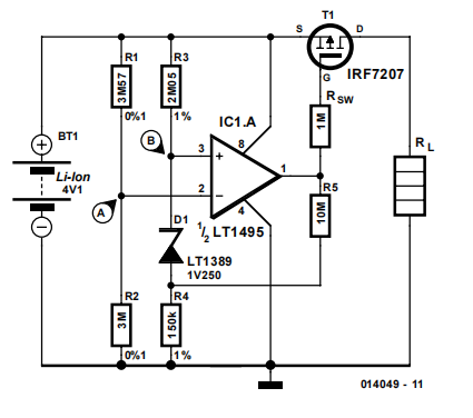
When a lithium-ion battery is discharged below the minimum recommended cell voltage its life expectancy is dramatically reduced. The circuit described here can avoid this by disconnecting the load from the battery when the cell voltage reaches a set level.The voltage at junction A may be set to 3 V, for example, by selecting the correct ratio of R1 and R2. When the battery voltage drops below the minimum value, the voltage at junction A will be smaller than that at junction B. The latter voltage is equal to: 

VB = 1.25 V + I R4 = 1.37 V

where:

I = (Vmin. – 1.25 V) / (R3 + R4) = 800 nA
(Vmin. = minimum value)

At this point the output of opamp LT1495 will go high, causing SW1 (a P-channel logic level MOSFET) to block and break the connection between the battery and the load. Because the battery voltage will rise when the load is disconnected, a certain amount of hysteresis is created by the addition of R5. This prevents the circuit from oscillating around the switching point. The value of R5 shown here provides 92 mV of hysteresis. So the battery voltage has to
rise to 3.092 V before the load is reconnected to the battery. An increase or decrease of the hysteresis is possible by reducing or increasing the value of R5, respectively. The required hysteresis depends in the internal impedance of the battery and the magnitude of the load current. The switching point defined by the values of R1-R2 is
quite critical with a circuit such as this. If the switching point is too high, then the available capacity of the battery is not fully utilised. Conversely, if the switching point is too low, the battery will be discharged too far with all the harmful consequences that may entail. Using the values shown here and including the tolerances of the parts, the switching point is between 2.988 V and 3.012 V. In practice it may be easier to select slightly lower values for R1 or R2 and connect a multi-turn trimpot in series with it. This makes an accurate adjustment of the switching point possible and has the additional advantage that R1 and R2 may be ordinary 1%-tolerance types.

Finally, before using the protection circuit it is advisable to first connect it to a power supply instead of a battery and carefully verify the operation of all its features!