Antenna Handbook

VHF Test Transmitter


If you want to be independent of the local radio stations for testing VHF receivers, you need a frequency modulated oscillator that covers the range of 89.5 to 108 MHz — but building such an oscillator using discrete components is not that easy. Maxim now has available a series of five integrated oscillator building blocks in the MAX260x series (see the May 2001 issue of Elektor Electronics), which cover the frequency range between 45 and 650 MHz. The only other thing you need is a suitable external coil, dimensioned for the midrange frequency. The MAX2606 covers the VHF band, although the frequency can only be varied by approximately ±3 MHz around the midrange frequency set by the coil L. The inductance values shown in the table can serve as starting points for further experimenting.The SMD coils of the Stettner 5503 series are suitable for such oscillators. In Germany, they are available from Bürklin (Buerklin.comwith values between 12 nH and 1200 nH. You can thus directly put together any desired value using two suitable coils. If you want to wind your own coils, try using 8 to 14 turns of 0.5-mm diameter silver-plated copper wire on a 5-mm mandrel. You can make fine adjustments to the inductance of the coil by slightly spreading or compressing the coil. The circuit draws power from a 9-V battery. The BC238C stabilises the voltage to approximately 4 V. Although the MAX2606 can work with a supply voltage between +2.7 V and +5.5 V, a stabilised voltage improves the frequency stability of the free-running oscillator. The supply voltage connection Vcc (pin 5) and the TUNE voltage (pin 3) must be decoupled by 1-nF capacitors located as close as possible to the IC pins. The tuning voltage TUNE on pin 3 may lie between +0.4 V and +2.4 V. A symmetric output is provided by the OUT+ and OUT– pins. In the simplest case, the output can be used in a single-ended configuration. Pull-up resistors are connected to each of the outputs for this purpose. You can use a capacitor to tap off the radio signal from either one of
these resistors. Several milliwatts of power are available. At the audio input, a signal amplitude of 10 to 20 mV is enough to generate the standard VHF frequency deviation of ±40 kHz.

Three Component Oscillator


At first glance, this circuit appears to be just a primitive microphone amplifier. Why then is the title of this article
‘Three-component Oscillator’? The answer is very simple:
the microphone is not intended to pick up speech; instead, it is placed so close to the loudspeaker that massive positive feedback occurs. Here we intentionally exploit an effect that is assiduously avoided in public-address systems — the positive feedback results in a terribly loud whistle. The loudspeaker is connected directly to the 12-V supply voltage and the power transistor, so it must be able to handle a power of at least 1.5 W, and it should have an impedance of 8 to 16 . An outstanding candidate can be cannibalised
from an old television set or discarded speaker box. The microphone should be a carbon-powder type from an old-fashioned telephone handset. If you place a switch in series with the power supply, this sound generator can also be used as an effective doorbell or siren. Surprisingly enough, the circuit can also be used as a simple microphone amplifier — hardly hi-fi, of course, but still usable.

source : P. Lay - Elektor Circuit Collections 

2.5-GHz Signal Source


More and more communications systems are operating in the 2.4-GHz ISM (Industrial, Scientific and Medical) band, including Blue
tooth, various WLAN (Wireless Local Area Network) and Home-RF systems. A simple test oscillator for the frequency band between 2.4 GHz and 2.5 GHz can prove useful in testing receivers. Such an oscillator is available from Maxim (www.maxim-ic.com) as a single IC. The MAX2750 covers the frequency range between 2,4 GHz and 2.5 GHz using in internal LC network that can be tuned using a varactor diode that is also built into the IC. An output buffer delivers a level of –3 dBm into 50 .
This component is housed in an 8-pin µMAX package. The circuit is powered from a 9-V battery. The BC238C transistor stabilises the battery voltage at around 4 V. Although the MAX2750 can work with supply voltages
between +2.7 V and +5.5 V, the frequency stability of the free-running oscillator is better with a stabilised supply voltage. All connections to the IC are decoupled using 220pF capacitors, which must be located as close as possible to the IC pins. The tuning voltage at pin 2, TUNE, may lie between +0.4 V and +2.4 V, which provides a tuning range between 2.4 GHz and 2.5 GHz. If it is desired to switch off the oscillator, this can be done by connecting the Shutdown input (SHDN) to earth potential. When the IC is shut down, its current consumption drops to around 1 µA. Here the shutdown input is connected to the Vcc potential by a pull-up resistor, so that the oscillator runs. The –3 dB output level can be reduced using the indicated pi attenuator. A number of resistance values for this attenuator are shown in the table.

source: Elektor Circuit Collections 

Step-up Switching Regulator with Integrated Current Limit


In the form of the LT1618, Linear Technology (www.lineartech.com) has made available a step-up switching regulator with a current limit mechanism. This makes it easy to protect an otherwise not short-circuit-proof switching regulator: the input voltage is always connected to the output via an inductor and a diode. We can limit the current at the input (Figure 1), which limits the current drawn by the entire circuit; alternatively, with the circuit of Figure 2, the output current can be limited. This enables the design of constant current sources at voltages higher than the input voltage. In the circuit shown the nominal output voltage of the step-up switching regulator will be around 22 V. The output voltage can be calculated using the formula

Vout = 1.263 V (1+R1/R2)

The output current can be set via R3 as follows:

Imax = Vsense / R3
where Vsense = 50 mV

The IADJ input can be set to a voltage between 0 V and +1.58 V resulting in a linear reduction of the limit current.
The sense voltage of 50 mV across R3 for maximum current is reduced as follows:

Vsense = 0.04 (1.263 V – 0.8 VIADJ )

Hence, for a fixed value of R3, the VIADJ input allows the current limit to be adjusted. Note that in the first circuit the sense resistor R3 is fitted between the input electrolytic capacitor and the inductor. If R3 is fitted before the capacitor, the inductor current can not be properly controlled.
The LT1618 operates on input voltages between +1.6 V and +18 V. Its output voltage must lie between Vin and +35 V. With a switching current of 1 A through pin SW to ground, an output current of around 100 mA can be expected. The switching frequency of the IC is about 1.4 MHz, and the device is available in a 10-pin compact MSOP package.

Li-Ion Protection Circuit


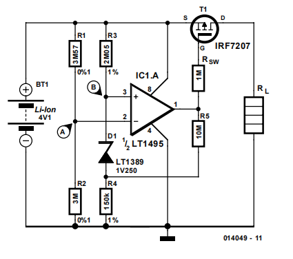
When a lithium-ion battery is discharged below the minimum recommended cell voltage its life expectancy is dramatically reduced. The circuit described here can avoid this by disconnecting the load from the battery when the cell voltage reaches a set level.The voltage at junction A may be set to 3 V, for example, by selecting the correct ratio of R1 and R2. When the battery voltage drops below the minimum value, the voltage at junction A will be smaller than that at junction B. The latter voltage is equal to: 

VB = 1.25 V + I R4 = 1.37 V

where:

I = (Vmin. – 1.25 V) / (R3 + R4) = 800 nA
(Vmin. = minimum value)

At this point the output of opamp LT1495 will go high, causing SW1 (a P-channel logic level MOSFET) to block and break the connection between the battery and the load. Because the battery voltage will rise when the load is disconnected, a certain amount of hysteresis is created by the addition of R5. This prevents the circuit from oscillating around the switching point. The value of R5 shown here provides 92 mV of hysteresis. So the battery voltage has to
rise to 3.092 V before the load is reconnected to the battery. An increase or decrease of the hysteresis is possible by reducing or increasing the value of R5, respectively. The required hysteresis depends in the internal impedance of the battery and the magnitude of the load current. The switching point defined by the values of R1-R2 is
quite critical with a circuit such as this. If the switching point is too high, then the available capacity of the battery is not fully utilised. Conversely, if the switching point is too low, the battery will be discharged too far with all the harmful consequences that may entail. Using the values shown here and including the tolerances of the parts, the switching point is between 2.988 V and 3.012 V. In practice it may be easier to select slightly lower values for R1 or R2 and connect a multi-turn trimpot in series with it. This makes an accurate adjustment of the switching point possible and has the additional advantage that R1 and R2 may be ordinary 1%-tolerance types.

Finally, before using the protection circuit it is advisable to first connect it to a power supply instead of a battery and carefully verify the operation of all its features!