Antenna Handbook

Yagi Antenna

The fundamentals of our antenna project are described through basic antenna characteristics. In general this starts with establishing the antenna’s radiation pattern, gain and directivity.  The radiation pattern is a 2-D or 3D plot which assesses the intensity in which electromagnetic waves propagates as a function of orientation. The gain of an antenna indicates how well the signal power amplifies in one direction, where its directivity characterizes the direction and magnitude of maximum power amplification. 

 The design of a Yagi (Yagi-Uda) antenna requires proper understanding of how the components are structured and how varying the lengths and position of these components changes the characteristics of the antenna. The components include a driver, reflector(s), and a number of directors.  The driver is the single active element which is excited by a signal, while the reflector(s) re-radiate by reflecting the signal and directors re-radiate by directing the signal. For this reason both the reflector(s) and directors are considered as parasitic elements.  A common starting point for a design begins with selecting the length of the director such that is it slightly less than one-half of the intended operating wavelength. In the report other general guidelines and specific details showcase the design choices as they relate to antenna performance.  In addition to our design we have examined the characteristics of a commercially available Yagi Antenna that being the WSJ-1800 which operates at 2.4 GHz as well. 


Theory 

 Antennas are devices that transmit or receive electromagnetic waves. If an antenna is receiving a signal it converts the incident electromagnetic waves into electrical currents; if it is transmitting it does the opposite. Antennas are designed to radiate (or receive) electromagnetic energy with particular radiation and polarization properties suited for its specific application. The Yagi antenna is a directional antenna which consists of a dipole and several parasitic elements. 

The parasitic elements in a Yagi antenna are the reflectors and the directors. A Yagi antenna typically has only one reflector which is slightly longer than the driving element (dipole) and several directors, which are slightly shorter than the driving element. The Yagi antenna is said to be directional because it radiates power in one direction allowing it to transmit and receive signals with less interference in that particular direction. Figure 1 is a diagram of the general configuration of a Yagi antenna. 

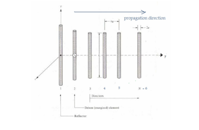
Figure 1. Yagi Antenna Configuration 


The directionality of an antenna can be determined from the relative distribution characteristics of the radiated power from the antenna; this is known as an antenna’s radiation pattern. Given the electric and magnetic field patterns of an antenna, the time average Poynting vector, also known as the power density equation, can be obtained using the following formula:


Where E and H are the electric and magnetic field equations. The radiation pattern is typically described in terms the normalized radiation intensity, which is given by: 

Where R is the range, θ is the called the elevation plane which corresponds to a constant value of φ . If φ = 0 then the x-z plane is defined. The φ angle is referenced through the azimuth plane and specified by θ = 90° (x-y plane). Figure 2 summarizes these parameters. 

Figure 2. Definition of R ,θ , andφ . 

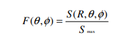
The radiation pattern of a Half-Wave Dipole Antenna is shown below. Once the electric and magnetic field equations for the Half-Wave Dipole Antenna are solved then a radiation pattern can be calculated. Please refer to the Appendix for the derivation of the electric and magnetic wave equations which lead to the calculation of the radiation pattern.

 Figure 3. Half-Wave Dipole Antenna and Radiation Pattern


Notice that the Half-Wave Dipole Antenna radiates its power equally in a radial fashion, along the x-y plane in Figure 3. The radiation pattern for a commercial MFJ-1800, a 2.4 GHz Wi-Fi operation Yagi antenna is shown below. Refer to the Appendix for an abbreviated derivation of the radiation pattern of a Yagi antenna. 

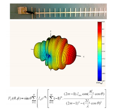
Figure 4. MFJ-1800 Yagi Antenna and its Radiation Patten 


Notice that the radiation pattern shows a very directive beam, which indicates that the MFJ-1800 Yagi Antenna radiates with the greatest directional power along the xdirection. The general guidelines for determining the size and shape of a Yagi antenna include accounting for the reflector length, driver length, director lengths, reflector to driver spacing, driver to first director spacing, and the spacing between the directors. The directional gain of a Yagi antenna is typically 7-9dB per λ (wavelength) of overall antenna length (given as a multiple of wavelengths). 

There is little to no gain by the addition of more than one reflector. Adding directors however, does increases the overall directive gain of the antenna, but not indefinitely. Generally the reflector length is slightly greater than λ/2, the driver and director lengths are slightly less than λ/2, director lengths are typically between 0.4-0.45λ. The reflector to driver spacing is about λ/4. 

The spacing between directors can be between n 0.2 to 0.4λ, but be aware when the director spacing is greater than 0.3λ the overall gain of the antenna is decreased by 5-7dB. Procedure The Yagi antenna that was built for this project was made from an aluminum sheet. The aluminum sheet was cut out using pliers and filed down to the specific dimensions. The driving element was shaped from a thin plastic sheet and then covered with copper tape. 

The Yagi antenna was built this way for two reasons: the aluminum sheet and copper tape were cheap and also easy to work with. The drawback of cutting out the Yagi antenna from an aluminum sheet was that the design became final upon cutting and no further adjustments are then possible.


Figure 5. Cutting out the parasitic elements. The final design. 


Figure 6 is a general schematic of the Yagi antenna which was built. The six lengths that are listed in the schematic are of the specific lengths that were previously explained. The list below summarizes those lengths.

 λ = c / f = (3x10⁸ ) / (2.4*109 ) = 0.125m = 125 mm 
L1 (director spacing) ≈ 42 mm = 0.34 λ 
L2 (driver to director) ≈ 35 mm = 0.28 λ 
L3 (reflector to driver) ≈ 35 mm = 0.28 λ 
L4 (directors length, < (λ/2) < L5) ≈ 41 mm = 0.33 λ 
L5 (driver length, < (λ/2)) ≈ 60 mm = 0.48 λ 
L6 (reflector length, > L5 > (λ>2)) ≈ 64 mm = 0.51 λ 
L7 (antenna length) ≈ 200 mm = 1.6 λ 
Expected gain = 1.6 λ (7dB/ λ) – 5dB = 6.2dB

The expected gain is antenna gain was calculated by using two of the general rules for designing a Yagi antenna. These rules were described in the Theory section of this report. Expect a 7-9dB gain per λ (overall length of antenna) and also a 5-7dB loss if the director lengths exceed 0.3 λ. In our design the antenna was 1.6 λ in total length and the drivers were slightly over 0.3 λ so we naturally assumed about a 5dB loss.


In order to determine how our Yagi antenna would radiate we decided to use a very common software application which calculated and plotted the three dimensional radiation patterns for typical antennas. This professional software tool is called Super NEC 2.9, which we obtained a 30-day trial version which has functions that integrated with MATLAB. Super NEC has a built-in template for a Yagi antennas which allowed us to simply input the Yagi antenna’s element spacing’s and Super NEC generated a three dimensional model of the antenna, as shown in Figure 7. 


Once the antenna has the desired dimensions, then Super NEC can generate three dimensional radiation plots of the antenna. As shown on Figure 8. 

As expected the predicted directivity gain (at max) is 6.2dB, which aligned with our predicted expectations. 

Results 

 We verified our design at Palm, Inc. Palm has a calibrated setup for measuring radiation patterns of antennas. The first step that was taken prior to placing the antenna in a chamber for measurements was to verify that the antenna could in fact transmit a signal. With the use of a spectrum analyzer the S11 parameter was measured; if the S11 had been 0dBm this indicates the entire signal that is being put into the antenna is reflected back and not transmitted at all. Ideally we want the S11 to be as low as possible at the desired operating frequency. 

As the graph shows the antenna transmitted the best at about 2.3GHz, which is not the intended frequency of 2.4GHz, yet it still performs well at 2.4GHz with the S11 parameter at -6dB. This low value indicates that the antenna does transmit at the operating frequency, but could improve its efficiency from a more optimized design. 

 Once we verified that the Yagi antenna did in fact transmit then we placed it in the radiation chamber (Figure 10). Inside this chamber the antenna is mechanically rotated while an automated program gathered all the relevant data then generated a three dimensional radiation pattern graph as shown in Figure 11. The measured radiation pattern yielded 5.54dB gain which is 0.7dB less than what we had expected.


Reference : EE 172 Extra Credit Project 2.4 GHz Yagi-Uda Antenna Created by Mario Delgadillo Maringan Pardamean Panggabean , San Jose University

Which NETGEAR Unmanaged PoE Switch is right for you?

Gigabit Ethernet Ports with 5 Ports with 4 x PoE with PoE 55 Watt

Unmanaged Switch: Plug and play solution to connect all your network devices without the complications of configuration or management software -- yet achieve a reliable and secure network.


NETGEAR Unmanaged PoE Switch Advantages
Designed for Whisper-Quiet Operation: Most switch models are fanless or designed to minimize fan noise to protect your business environment.
Power Saving and Energy Efficient: We care about saving energy for your business so our switches are compliant with IEEE802.3az Energy Efficient Ethernet mode.
Plug-and-Play: No configuration necessary - perfect for small-medium businesses.

Smart Managed Plus: Empowers growing small businesses with basic capabilities to configure, secure, and monitor their network beyond simple connectivity at an affordable cost - an ideal upgrade from unmanaged switches.


Best Sony TV Deals Bravia 85 Inch Works with Alexa


Sony HDTV 4K with HDR Technology and Processor X1 Ultimate Technology from Sony, with intelligent processing and ultimate realism , make Sony TV 85 Inch Enhanced have Contrast Brightness in color.

With 4K-X Reality Pro, you experience more natural picture and object based super resolution . Alexa inside Sony 85 Inch TV with Android Operating Systems and Amazon account , enable smart device connected and controlled via Alexa. You can talk with Alexa and asking Alexa to turn on or off your device , switch channel TV, show your front door bedroom via camera, and others smart devices connected to Alexa.


From Manufacturer Video Sony XBR85X950G X950G 85 Inch TV: 4K Ultra HD Smart LED TV with HDR and Alexa Compatibility . Check It Out !


Zero Energy Device Example

“Free-Energy Devices” or “Zero-Point Energy Devices” are the names applied to systems which appear to produce a higher output power than their input power.  

There is a strong tendency for people to state that such a system is not possible since it contravenes the Law of Conservation of Energy.  It doesn’t.  If it did, and any such system was shown to work, then the “Law” would have to be modified to include the newly observed fact.  No such change is necessary, it merely depends on your point of view. 

For example, consider a crystal set radio receiver:


Fig 1 . Crystal Set


Looking at this in isolation, we appear to have a free-energy system which contradicts the Law of Conservation of Energy.  It doesn’t, of course, but if you do not view the whole picture, you see a device which has only passive components and yet which (when the coil is of the correct size) causes the headphones to generate vibrations which reproduce recognisable speech and music.  

This looks like a system which has no energy input and yet which produces an energy output.  Considered in isolation, this would be a serious problem for the Law of Conservation of Energy, but when examined from a common sense point of view, it is no problem at all.   


The whole picture is: 
Fig 2. Crystal Set whole Picture

Power is supplied to a nearby transmitter which generates radio waves which in turn, induce a small voltage in the aerial of the crystal set, which in turn, powers the headphones.  The power in the headphones is far, far less than the power taken to drive the transmitter.  

There is most definitely, no conflict with the Law of Conservation of Energy.  However, there is a quantity called the “Coefficient Of Performance” or “COP” for short.  This is defined as the amount of power coming out of a system, divided by the amount of power that the operator has to put into that system to make it work.  In the example above, while the efficiency of the crystal set radio is well below 100%, the COP is greater than 1.  

This is because the owner of the crystal radio set does not have to supply any power at all to make it work, and yet it outputs power in the form of sound.  As the input power from the user, needed to make it work is zero, and the COP value is calculated by dividing the output power by this zero input power, the COP is actually infinity. 

 Efficiency and COP are two different things.  Efficiency can never exceed 100% and almost never gets anywhere near 100% due to the losses suffered by any practical system. 

Reference :https://www.free-energy-info.com/

Antennas Direct ClearStream Eclipse TV Antenna for 35+ Miles - 55+ KM Range

ClearStream Eclipse Sure Grip HDTV Antenna


35 Mile Range

The ClearStream Eclipse Sure Grip TV Antenna with new advanced performance to receive a greater range of frequencies 35 miles from the broadcast towers. Grips to any smooth surface, such as a wall or window. Great for dorm rooms, RV's and over-the-road vehicles. It features a black or white double-sided design and is paintable, so you can match your wall, furniture, or accent color for a custom fit.

Setup is Easy


Antennas Direct ClearStream Eclipse TV Antenna, 35+ Miles/55+ KM Range, Multi-Directional, Grips to Walls/Windows with Sure Grip Strip, 12 ft. RG-6 Cable,...
Clearstream ECLIPSE Amplified TV Antenna, 50+ Mile Range, Multi-Directional, Grips to Walls, 20dB In-Line Signal Amplifier, 15 ft. Coaxial Cable, 5 ft. USB...

Pros :
  • Suitable for Down Town House
  • Indoor Antenna
  • Suitable for Apartment

Cons :
  • Need Line Of Sight Glass Wall/Door


Antennas Direct ClearStream 2V TV Antenna, 60+ Mile Range, UHF/VHF, Multi-directional, Indoor, Attic, Outdoor, Mast w/Pivoting Base/Hardwar/ Adjustable... Style:60 Mile
Pros :

  • Long range Antenna 
  • Multifunction Antenna VHF/UHF
  • Indoor / Outdoor Antenna

Cons :
  • Better use 70 miles Eclipse antenna Outdoor for maximize reception
  • Need Tools for Outdoor Installation
70 Miles Eclipse Antenna    


Antennas Direct Clearstream 4V TV Antenna, 70+ Mile Range, UHF/Vhf, Multi-Directional, Indoor, Attic, Outdoor, Mast W/Pivoting Base/Hardware/Adjustable... Style:70 Miles

Pros :

  • Long Range Antenna Receiver 
  • Indoor / Outdoor Function

Cons :
  • Big in Size Antenna
  • Need Tools for Outdoor Installation


Reduce Your Monthly TV Bill


You can now experience HDTV in the highest quality picture and sound available. Over-the-air broadcasts are transmitted in crystal clear Full HD 1080; far less compressed than what cable and satellite offer. Many local broadcasts are digitally aired in 5.1 Surround Sound giving you the ultimate sound stage for watching live television. With a digital TV antenna you can receive free local news, weather, kids shows, sports, cooking, shopping, and sitcoms from networks like ABC, NBC, CBS, FOX, PBS, CW, ION, and much more, with no cost or contracts. Broadcast TV won't be interrupted from service drop outs. Quick fact: local sports are broadcast free over-the-air. You just need an antenna.

Network Antenna Analyzer

For 10KHz-1.5GHz MF HF VHF UHF
Measuring S parameters, voltage standing wave ratio, phase, delay, Smith chart and the like


What are S-parameters? 
S-parameters are complex matrix that show Reflection/Transmission characteristics (Amplitude/Phase) in frequency domain. This type of test equipment is called “Stimulus/Response” and applies to both Vector Network Analyzers (VNA) and Time Domain Reflectometers (TDR). A two-port device has four S-parameters. The numbering convention for S-parameters is that the first number following the “S” is the port where the signal emerges, and the second number is the port where the signal is applied. So S21 is a measure of the signal coming out port 2 relative to the RF stimulus entering port 1. When the numbers are the same (e.g., S11), in indicates a reflection measurement, as the input and output ports are the same.

2.8 TFT Touchscreen

You can move the mark point or perform a menu operation via your hand directly or multi-functional switch.You could also rotate the wheel to operate it. Pressing is confirm.Left/Right rotation to move the selection.

10kHz-1.5GHz Frequency

New Upgraded! The measurement frequency up to 1.5GHz.Based on odd harmonic extension of si5351,new upgraded version- NanoVNA-H will transmit the signal with maximum efficiency and minimum distortion. Frequency Accuracy: 0.5PPM.

USB-C to USB-C

Compare with old version NanoVNA, it supports time domain analysis function (TDR), and more convenient to connect to mobile phones. Compatible with most Android mobile phones.
Support Windows Computer Control
Output Graph

Nonresonant single-wire longwire antennas


The resonant longwire antenna is a standing wave antenna, because it is unterminated at the far end. A signal propagating from the feedpoint, toward the open end, will be reflected back toward the source when it hits the open end. The interference between the forward and reflected waves sets up stationary standing current and voltage waves along the wire.

A nonresonant longwire is terminated at the far end in a resistance equal to its characteristic impedance. Thus, the incident waves are absorbed by the resistor, rather than being reflected. Such an antenna is called a traveling wave antenna. Figure 9-8 shows a terminated longwire antenna. 

The transmitter end is like the feed system for  other longwire antennas, but the far end is grounded through a terminating resistor R1 that has a resistance R equal to the characteristic impedance Zo of the antenna (i.e., R = Zo). When the wire is 20 to 30 ft above the ground, Zo is about 500 to 600 Ω.

The radiation pattern for the terminated longwire is a unidirectional version of the multilobed pattern found on the unterminated longwires. The angles of the lobes vary with frequency, even though the pattern remains unidirectional. 

The directivity of the antenna is partially specified by the angles of the main lobes. It is interesting to note that gain rises almost linearly with nλ, while the directivity function changes rapidly at shorter lengths (above three or four wavelengths the rate of change diminishes considerably). 

Thus, when an antenna is cut for a certain low frequency, it will work at higher frequencies, but the directivity characteristic will be different at each end of the spectrum of interest.

A two-wavelength (2λ) pattern is shown in Fig. 9-7. There are four major lobes positioned at angles of ±36° from the longwire. There are also four minor lobes— the strongest of which is –5 dB down from the major lobes—at angles of ±75° from the longwire. Between all of the lobes, there are sharp nulls in which little reception is possible. 

As the wire length is made longer, the angle of the main lobes pulls in tighter (i.e., toward the wire). As the lobes pull in closer to the wire, the number of minor lobes increases. At 5λ, there are still four main lobes, but they are at angles of ±22°from the wire. Also, the number of minor lobes increases to 16. 

The minor lobes are located at ±47°, ±62°, ±72°, and ±83° with respect to the wire. The minor lobes tend to be –5 to –10 dB below the major lobes. When the longwire gets very much longer than 5λ, the four main lobes begin to converge along the length of the wire, and the antenna becomes bidirectional. This effect occurs at physical lengths greater than about 20λ.


In general, the following rules apply to longwire antennas:

• On each side of the antenna, there is at least one lobe, minor or major, for each half-wavelength of the wire element. For the overall element, there is one lobe for every quarter-wavelength.

• If there are an even number of lobes on either side of the antenna wire, then half of the total number of lobes are tilted backward, and half are tilted forward; symmetry is maintained.

• If there are an odd number of lobes on either side of the wire, then one lobe on either side will be perpendicular to the wire, with the other lobes distributed either side of the perpendicular lobe.

True longwire antennas

Figure 9-5 shows the true resonant longwire antenna. It is a horizontal antenna, and if properly installed, it is not simply attached to a convenient support (as is true with the random length antenna). Rather, the longwire is installed horizontally like a dipole. The ends are supported (dipole-like) from standard end insulators and rope.

The feedpoint of the longwire is one end, so we expect to see a voltage antinode where the feeder is attached. For this reason we do not use coaxial cable, but rather either parallel transmission line (also sometimes called open-air line or some such name), or 450-Ωtwin lead. The transmission line is excited from any of several types of balanced antenna tuning unit (see Fig. 9-5). Alternatively, a standard antenna tuning unit (designed for coaxial cable) can be used if a 4:1 balun transformer is used between the output of the tuner and the input of the feedline. What does “many wavelengths” mean? That depends upon just what you want the antenna to do. Figure 9-6 shows a fact about the longwire that excites many users of longwires: It has gain! Although a two-wavelength antenna only has a slight gain over a dipole; the longer the antenna, the greater the gain. In fact, it is possible to obtain gain figures greater than a three-element beam using a longwire, but only at nine or ten wavelengths.
What does this mean? One wavelength is 984/FMHz ft, so at 10 m (29 MHz) one wavelength is about 34 ft; at 75 m (3.8 MHz) one wavelength is 259 ft long. In order to meet the two-wavelength criterion a 10-m antenna need only be 68 ft long, while a 75-m antenna would be 518 ft long! For a ten-wavelength antenna, therefore, we would need 340 ft for 10 m; and for 75 m, we would need nearly 2,600 ft. Ah me, now you see why the longwire is not more popular. The physical length of a nonterminated resonant longwire is on the order of


Of course, there are always people like my buddy (now deceased) John Thorne, K4NFU. He lived near Austin, TX on a multiacre farmette that has a 1400ft property line along one side. John installed a 1300 ft longwire and found it worked excitingly well. He fed the thing with homebrew 450-Ω parallel (open-air) line and a Matchbox antenna tuner. John’s longwire had an extremely low angle of radiation, so he regularly (much to my chagrin on my small suburban lot) worked ZL, VK, and other Southeast Asia and Pacific basin DX, with only 100 W from a Kenwood transceiver.

Oddly enough, John also found a little bitty problem with the longwire that textbooks and articles rarely mention: electrostatic fields build up a high-voltage dc charge on longwire antennas! Thunderstorms as far as 20 mi away produce serious levels of electrostatic fields, and those fields can cause a buildup of electrical charge on the antenna conductor. The electric charge can cause damage to the receiver. John solved the problem by using a resistor at one end to ground. The “resistor” is composed of ten to twenty 10-MΩ resistors at 2 W each. This resistor bleeds off the charge, preventing damage to the receiver.

A common misconception about longwire antennas concerns the normal radiation pattern of these antennas. I have heard amateurs, on the air, claim that the maximum radiation for the longwire is

1. Broadside (i.e., 90°) with respect to the wire run or
2. In line with the wire run

Neither is correct, although ordinary intuition would seem to indicate one or the other. Figure 9-7 shows the approximate radiation pattern of a longwire when viewed from above. There are four main lobes of radiation from the longwire (A, B, C, and D). There are also two or more (in some cases many) minor lobes (E and F) in the antenna pattern. The radiation angle with respect to the wire run (G–H) is a function of the number of wavelengths found along the wire. Also, the number and extent of the minor lobes is also a function of the length of the wire.

Quad Beam Antennas

The quad antenna was introduced in the chapter on beams. It is, nonetheless, also emerging as a very good VHF/UHF antenna. It should go without saying that the antenna is a lot easier to construct at VHF/UHF frequencies than it is at HF frequencies! Figure 18-13 shows a modest example. 

There are several methods for building the quad antenna, and Fig. 18-13 represents only one of them. The radiator element can be any of several materials, including heavy solid wire (no. 8 to no. 12), tubing, or metal rods. The overall lengths of the elements are given by:


There are several alternatives for making the supports for the radiator. Because of the lightweight construction, almost any method can be adapted for this purpose.

 In the case shown in Fig. 18-13, the spreaders are made from either 1-in furring strips, trim strips, or (at above 2 m) even wooden paint stirring sticks. The sticks are cut to length, and then half-notched in the center (Fig. 18-13, detail B). 

The two spreaders for each element are joined together at right angles and glued (Fig. 18-13, detail C). The spreaders can be fastened to the wooden boom at points S in detail C. The usual rules regarding element spacing (0.15 to 0.31 wavelength) are followed. 

See the information on quad antennas in Chap. 12 for further details. Quads have been successfully built for all amateur bands up to 1296 MHz.


Halo Antennas

One of the more saintly antennas used on the VHF boards is the halo (Fig. 18-12). This antenna basically takes a half-wavelength dipole and bends it into a circle. 

The ends of the dipole are separated by a capacitor. In some cases, a transmitting-type mica “button” capacitor is used, but in others (and perhaps more commonly), the halo capacitor consists of two 3-in disks separated by a plastic dielectric. 

While air also serves as a good (and perhaps better) dielectric, the use of plastic allows mechanical rigidity to the system.

Groundplane Antennas


The groundplane antenna is a vertical radiator situated above an artificial RF ground consisting of quarter-wavelength radiators. Groundplane antennas can be either 1⁄4-wavelength or 5⁄8-wavelength (although for the latter case impedance matching is needed—see the previous example).

Figure 18-11 shows how to construct an extremely simple groundplane antenna for 2 m and above. The construction is too lightweight for 6-m antennas (in general), because the element lengths on 6-m antennas are long enough to make their weight too great for this type of construction. The base of the antenna is a single SO-239 chassis-type coaxial connector. Be sure to use the type that requires four small machine screws to hold it to the chassis, and not the single-nut variety.

The radiator element is a piece of 3⁄16-in or 4-mm brass tubing. This tubing can be bought at hobby stores that sell airplanes and other models. The sizes quoted just happen to fit over the center pin of an SO-239 with only a slight tap from a lightweight hammer—and I do mean slight tap. If the inside of the tubing and the connector pin are pretinned with solder, then sweat soldering the joint will make a good electrical connection that is resistant to weathering. Cover the joint with clear lacquer spray for added protection.


The radials are also made of tubing. Alternatively, rods can also be used for this purpose. At least four radials are needed for a proper antenna (only one is shown in Fig. 18-11). This number is optimum because they are attached to the SO-239 mounting holes, and there are only four holes. Flatten one end of the radial, and drill a small hole in the center of the flattened area. Mount the radial to the SO-239 using small hardware (4-40, etc.).

The SO-239 can be attached to a metal L bracket. While it is easy to fabricate such a bracket, it is also possible to buy suitable brackets in any well-equipped hardware store. While shopping at one do-it-yourself type of store, I found several reasonable candidate brackets. The bracket is attached to a length of 2 2-in lumber that serves as the mast.

J Pole Antennas

The J-pole antenna is another popular form of vertical on the VHF bands. It can be used at almost any frequency, although the example shown in Fig. 18-10 is for 2 m. The antenna radiator is 3⁄4-wavelength long, so its dimension is found from

Taken together the matching section and the radiator form a parallel transmission line with a characteristic impedance that is 4 times the coaxial cable impedance. If 50-Ω coax is used, and the elements are made from 0.5 in OD pipe, then a spacing of 1.5 in will yield an impedance of about 200 Ω. Impedance matching is accomplished by a gamma match consisting of a 25-pF variable capacitor, connected by a clamp to the radiator, about 6 in (experiment with placement) above the base.