Style Social Media Buttons

Yagi Antenna

The fundamentals of our antenna project are described through basic antenna characteristics. In general this starts with establishing the antenna’s radiation pattern, gain and directivity.  The radiation pattern is a 2-D or 3D plot which assesses the intensity in which electromagnetic waves propagates as a function of orientation. The gain of an antenna indicates how well the signal power amplifies in one direction, where its directivity characterizes the direction and magnitude of maximum power amplification. 
 The design of a Yagi (Yagi-Uda) antenna requires proper understanding of how the components are structured and how varying the lengths and position of these components changes the characteristics of the antenna. The components include a driver, reflector(s), and a number of directors.  The driver is the single active element which is excited by a signal, while the reflector(s) re-radiate by reflecting the signal and directors re-radiate by directing the signal. For this reason both the reflector(s) and directors are considered as parasitic elements.  A common starting point for a design begins with selecting the length of the director such that is it slightly less than one-half of the intended operating wavelength. In the report other general guidelines and specific details showcase the design choices as they relate to antenna performance.  In addition to our design we have examined the characteristics of a commercially available Yagi Antenna that being the WSJ-1800 which operates at 2.4 GHz as well. 


Theory 

 Antennas are devices that transmit or receive electromagnetic waves. If an antenna is receiving a signal it converts the incident electromagnetic waves into electrical currents; if it is transmitting it does the opposite. Antennas are designed to radiate (or receive) electromagnetic energy with particular radiation and polarization properties suited for its specific application. The Yagi antenna is a directional antenna which consists of a dipole and several parasitic elements. 

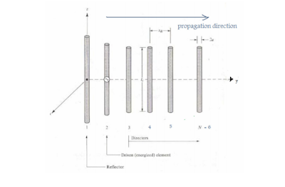
The parasitic elements in a Yagi antenna are the reflectors and the directors. A Yagi antenna typically has only one reflector which is slightly longer than the driving element (dipole) and several directors, which are slightly shorter than the driving element. The Yagi antenna is said to be directional because it radiates power in one direction allowing it to transmit and receive signals with less interference in that particular direction. Figure 1 is a diagram of the general configuration of a Yagi antenna. 

Figure 1. Yagi Antenna Configuration 


The directionality of an antenna can be determined from the relative distribution characteristics of the radiated power from the antenna; this is known as an antenna’s radiation pattern. Given the electric and magnetic field patterns of an antenna, the time average Poynting vector, also known as the power density equation, can be obtained using the following formula:


Where E and H are the electric and magnetic field equations. The radiation pattern is typically described in terms the normalized radiation intensity, which is given by: 

Where R is the range, θ is the called the elevation plane which corresponds to a constant value of φ . If φ = 0 then the x-z plane is defined. The φ angle is referenced through the azimuth plane and specified by θ = 90° (x-y plane). Figure 2 summarizes these parameters. 

Figure 2. Definition of R ,θ , andφ . 

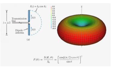
The radiation pattern of a Half-Wave Dipole Antenna is shown below. Once the electric and magnetic field equations for the Half-Wave Dipole Antenna are solved then a radiation pattern can be calculated. Please refer to the Appendix for the derivation of the electric and magnetic wave equations which lead to the calculation of the radiation pattern.

 Figure 3. Half-Wave Dipole Antenna and Radiation Pattern


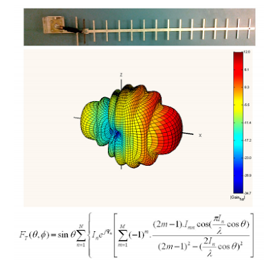
Notice that the Half-Wave Dipole Antenna radiates its power equally in a radial fashion, along the x-y plane in Figure 3. The radiation pattern for a commercial MFJ-1800, a 2.4 GHz Wi-Fi operation Yagi antenna is shown below. Refer to the Appendix for an abbreviated derivation of the radiation pattern of a Yagi antenna. 

Figure 4. MFJ-1800 Yagi Antenna and its Radiation Patten 


Notice that the radiation pattern shows a very directive beam, which indicates that the MFJ-1800 Yagi Antenna radiates with the greatest directional power along the xdirection. The general guidelines for determining the size and shape of a Yagi antenna include accounting for the reflector length, driver length, director lengths, reflector to driver spacing, driver to first director spacing, and the spacing between the directors. The directional gain of a Yagi antenna is typically 7-9dB per λ (wavelength) of overall antenna length (given as a multiple of wavelengths). 

There is little to no gain by the addition of more than one reflector. Adding directors however, does increases the overall directive gain of the antenna, but not indefinitely. Generally the reflector length is slightly greater than λ/2, the driver and director lengths are slightly less than λ/2, director lengths are typically between 0.4-0.45λ. The reflector to driver spacing is about λ/4. 

The spacing between directors can be between n 0.2 to 0.4λ, but be aware when the director spacing is greater than 0.3λ the overall gain of the antenna is decreased by 5-7dB. Procedure The Yagi antenna that was built for this project was made from an aluminum sheet. The aluminum sheet was cut out using pliers and filed down to the specific dimensions. The driving element was shaped from a thin plastic sheet and then covered with copper tape. 

The Yagi antenna was built this way for two reasons: the aluminum sheet and copper tape were cheap and also easy to work with. The drawback of cutting out the Yagi antenna from an aluminum sheet was that the design became final upon cutting and no further adjustments are then possible.


Figure 5. Cutting out the parasitic elements. The final design. 


Figure 6 is a general schematic of the Yagi antenna which was built. The six lengths that are listed in the schematic are of the specific lengths that were previously explained. The list below summarizes those lengths.

 λ = c / f = (3x10⁸ ) / (2.4*109 ) = 0.125m = 125 mm 
L1 (director spacing) ≈ 42 mm = 0.34 λ 
L2 (driver to director) ≈ 35 mm = 0.28 λ 
L3 (reflector to driver) ≈ 35 mm = 0.28 λ 
L4 (directors length, < (λ/2) < L5) ≈ 41 mm = 0.33 λ 
L5 (driver length, < (λ/2)) ≈ 60 mm = 0.48 λ 
L6 (reflector length, > L5 > (λ>2)) ≈ 64 mm = 0.51 λ 
L7 (antenna length) ≈ 200 mm = 1.6 λ 
Expected gain = 1.6 λ (7dB/ λ) – 5dB = 6.2dB

The expected gain is antenna gain was calculated by using two of the general rules for designing a Yagi antenna. These rules were described in the Theory section of this report. Expect a 7-9dB gain per λ (overall length of antenna) and also a 5-7dB loss if the director lengths exceed 0.3 λ. In our design the antenna was 1.6 λ in total length and the drivers were slightly over 0.3 λ so we naturally assumed about a 5dB loss.


In order to determine how our Yagi antenna would radiate we decided to use a very common software application which calculated and plotted the three dimensional radiation patterns for typical antennas. This professional software tool is called Super NEC 2.9, which we obtained a 30-day trial version which has functions that integrated with MATLAB. Super NEC has a built-in template for a Yagi antennas which allowed us to simply input the Yagi antenna’s element spacing’s and Super NEC generated a three dimensional model of the antenna, as shown in Figure 7. 


Once the antenna has the desired dimensions, then Super NEC can generate three dimensional radiation plots of the antenna. As shown on Figure 8. 

As expected the predicted directivity gain (at max) is 6.2dB, which aligned with our predicted expectations. 

Results 

 We verified our design at Palm, Inc. Palm has a calibrated setup for measuring radiation patterns of antennas. The first step that was taken prior to placing the antenna in a chamber for measurements was to verify that the antenna could in fact transmit a signal. With the use of a spectrum analyzer the S11 parameter was measured; if the S11 had been 0dBm this indicates the entire signal that is being put into the antenna is reflected back and not transmitted at all. Ideally we want the S11 to be as low as possible at the desired operating frequency. 

As the graph shows the antenna transmitted the best at about 2.3GHz, which is not the intended frequency of 2.4GHz, yet it still performs well at 2.4GHz with the S11 parameter at -6dB. This low value indicates that the antenna does transmit at the operating frequency, but could improve its efficiency from a more optimized design. 

 Once we verified that the Yagi antenna did in fact transmit then we placed it in the radiation chamber (Figure 10). Inside this chamber the antenna is mechanically rotated while an automated program gathered all the relevant data then generated a three dimensional radiation pattern graph as shown in Figure 11. The measured radiation pattern yielded 5.54dB gain which is 0.7dB less than what we had expected.


Reference : EE 172 Extra Credit Project 2.4 GHz Yagi-Uda Antenna Created by Mario Delgadillo Maringan Pardamean Panggabean , San Jose University

No comments:

Post a Comment