Since no internet is needed, receiving free other-the-air stations is the only truly free TV option available.
If you live in a city, receiving a good broadcast signal is likely not a problem with the right TV antenna.
But what if you have a problem receiving a signal with pixelation and signal loss?
Thankfully there is an answer to this by using an over-the-air digital TV signal booster amplifier in combination with a TV antenna to get a good signal.
A booster can also help if multiple TVs are being used from the same antenna as the signal strength can degrade with multiple TVs pulling a signal.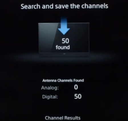
If you do use more than one TV, be sure to get an amplifier with more than one output port.
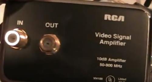
Installation is simple enough, with a coax cable going into the input and output to a TV. The booster will increase the signal power as it goes through the box.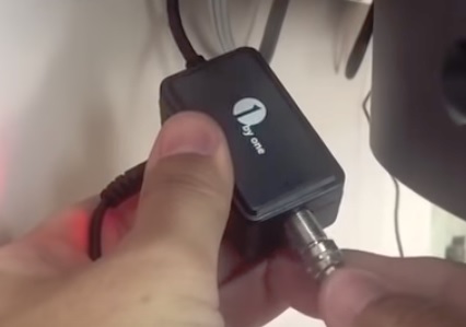
TV signal amplifiers can be outdoor or indoor, depending on your setup.
There are many units available, with some of our favorite picks below.
As always, be sure to read reviews on Amazon, forums, or elsewhere to be sure a unit is a right pick for you.
*This post contains affiliate links.
Our Picks for Best TV Antenna Over-The-Air Signal Boosters
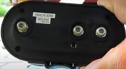
- Antennas Direct TV Distribution Amplifier
- 18db Gain
- Can be used with multiple TVs
- Limited to boosting 4 TVs
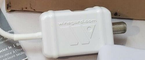
- Winegard LNA-200
- Preamplifier made to boost a TV signal
- Mounted at antenna to boost signal to multiple TVs
- Only works with non amplified antennas
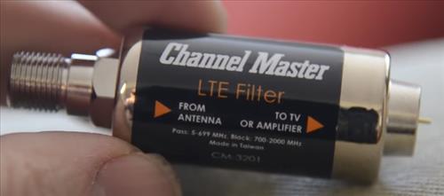
- Channel Master LTE Filter
- Filter out cell signals that can distort TV broadcast
- Improves TV signals when near a cell tower
- Will be no benefit in a low cell usage location
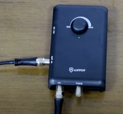
- ANTOP Smart Boost Amplifier
- Has a dial to adjust gain
- Amplifies FM, VHF and UHF signals
- Manually adjusting for multiple stations may cause issues
- Winegard LNA-100
- Small low-cost unit
- 20 dB Gain
- Only amplifies the signal for one TV
- Indoor use only
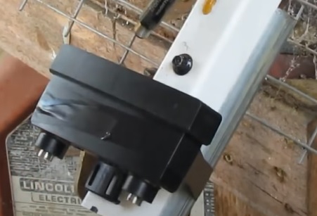
- RCA TVPRAMP1Z
- Preamp mounted at antenna to boost signal
- Amplifies UHF and VHF
- Needs to be mounted outside at antenna
- Antop Amplifier Signal Booster with 4G LTE Filter
- Amplifies FM UHF VHF signals
- 3G and 4G Filter
- Only amplifies the signal for one TV
- Indoor use only
Pros
Cons
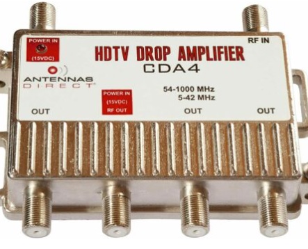
The Antennas Direct Amplifier has different packages with up to 8-Port for output depending on how many TVs you have.
The units can give an 18db gain per output for multiple TVs.
If you are getting bad to poor OTA TV reception, the Antennas Direct Amplifier is a good unit to get.
They also have many other amplifier boosters, including preamps and filters.
Pros
Cons
The Winegard LNA-200 is a newer improved unit from the LNA-100.
The LNA-200 costs more and may not be needed as the LNA-100 works well enough for basic boosting.
If you have a very bad signal, the LNA-200 model would be a much better unit to get.
Available Here on Amazon
Pros
Cons
Channel Master has many good products, including the LTE Filter, which gets rid of all the cellphone signals that can cause problems with TV broadcasts.
It will help with pixelation or channel loss in a highly used LTE area such as close to a cell tower or a big city.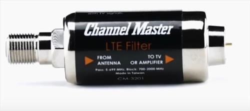
It is not an amplifier but a filter for spots where cell signals interrupt TV signals.
Some have had good success with the filter, while others see little to no results. It is a good unit if you live in a high-traffic LTE cellphone location.
Pros
Cons
The ANTOP Smart Boost Amplifier is built with a dial to help tune in the range of the TV signal.
It is a good unit that can help reduce freezing and pixelation caused by weak TV signals.
If you can receive TV stations but go in and out or are fuzzy, this is an excellent model to get a clearer signal.
As with most TV boosters, a signal will already need to be coming in with a booster, only helping to clear the signal up.
Pros
Cons
Winegard makes many good wireless products, including the LNA-100 amplifier.
It has a rated gain of 20dB, which makes it a good unit.
It uses a USB plug for power which most TVs have these days but be sure to check so the unit can get power.
Of course, a wall A/C USB power adapter can also be used if needed.
Pros
Cons
The RCA TVPRAMP1Z is an outdoor unit that pre-amplifies a signal before it goes into a home.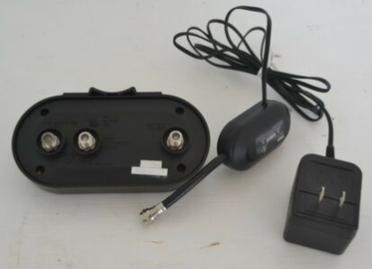
This makes it a good unit for anyone who needs to mount a TV signal booster outside.
Pros
Cons
Antop makes this low-cost High Gain Signal Booster that is small but effective.
The setup is easy by placing the inline booster between the antenna and TV on the coaxial line.
The kit comes with the inline signal booster, power cable, and USB wall charger if needed. Many TVs now have a USB port to plug into for power.
It is built for indoors and is a good low-cost booster for those on a budget.
Best OTA TV Antenna Amplifier Booster Comparison Chart
| NAME | PLUG TYPE | GAIN |
|---|---|---|
| Antennas Direct TV Distribution Amplifier | Coaxial | 18db |
| Winegard LNA-200 | Coaxial | 18 dB |
| Channel Master LTE Filter | Coaxial | ---- |
| ANTOP Smart Boost Amplifier | Coaxial | 14dB |
| Winegard LNA-100 | Coaxial | 20dB |
| RCA TVPRAMP1Z | Coaxial | 22db |
| Antop Signal Booster with 4G LTE Filter | Coaxial | 10dB |
Will an Antenna Booster Amplifier Give Me More Channels?
In many cases, yes, a booster or amplifier will bring in more stations.
The antenna will still need to receive a signal as an amplifier can only boost a signal.
If the signals are weak or pixelated, a booster amplifier will help receive a more clear signal.
A booster or amplifier can help greatly when a clearer picture is needed.
How Can I Boost My Digital TV Signal?
Installing an OTA booster or amplifier will greatly improve a TV signal.
There are many units available with our favorite picks above.
Can an OTA Booster Work on Multiple TVs?
Yes, there are many units that can not only boost a TV signal but also split it to work with multiple TVs.
In fact, a booster is often required when more than one TV is used since the signal can degrade.
When multiple TV sets are used a booster is set up to improve the signal.
What is the Difference Pre-Amplifier vs. Inline Amplifier
A pre-amplifier will boost the signal at the antenna giving maximum amplification.
An inline amplifier boosts the signal at any point on the line, usually at the TV.
Pre-amplifiers are a good option when multiple TV sets are used since they boost the antenna’s signal.
Inline amplifiers are a good option when a single TV is used, or only one set is having a problem, usually from a long coaxial run.
What Does a Booster Do for an Antenna?
An antenna is needed to receive an over-the-air TV signal and send it to a TV.
After a signal is received, a booster can be added to clear up a signal, getting rid of pixelation or bad reception.
A booster can not receive a signal; only improve a signal already being transmitted.
Can I Use Two Antenna Amplifiers?
Yes, more than one amplifier can be used, and it is very common.
Often a preamp is used at the antenna, and other inline boosters are added to a TV as needed.
Long coaxial runs can affect signal quality at times, with an inline unit needing to be added.
How Do You Install a Pre-Amplifier Signal Booster?
Most units screw onto the coaxial line with an input and output side.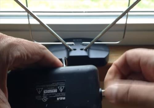
Inline units are often attached directly to a TV with the coaxial cable attached to it.
Pre-amplifiers are usually attached directly to the antenna boosting signal before it goes into a home.
Summary
If your digital over-the-air TV antenna is having problems getting a good signal, a booster can help.
There may be cases where the signal is just too far away, but a booster will be of real benefit in most scenarios.
Setting up a TV amplifier is simple as the line from the antenna simply plugs into the input, and the line-out goes to the TV.
There are many good boosters available, with those above simply some of our favorites.
Do you have a favorite TV signal booster? Let us know in the comments below.
source : https://www.wirelesshack.org/best-tv-antenna-over-the-air-signal-boosters.html


.PNG)


.PNG)


.PNG)
.PNG)
.PNG)
.PNG)
.PNG)
.PNG)

.PNG)
.PNG)
.PNG)

.PNG)

.PNG)
.PNG)

.PNG)
.PNG)