
What is Horn Antenna : Working & Its Applications
- A Horn antenna is a type of aperture antenna which is specially designed for microwave frequencies. The end of the antenna is widened or in the horn shape. Because of this structure, there is larger directivity so that the emitted signal can be easily transmitted to long distances. Horn antennas operate in microwave frequency, so the frequency range of these antennas is super high or ultra-high which ranges from 300 MHz – 30 GHz.The energy of the beam when slowly transform into radiation, the losses are reduced and the focussing of the beam improves. A Horn antenna may be considered as a flared out wave guide, by which the directivity is improved and the diffraction is reduced. One of the first horn antennas was constructed in 1897 by Bengali-Indian radio researcher Jagadish Chandra Bose in his pioneering experiments with microwaves. The modern horn antenna was invented independently in 1938 by Wilmer Barrow and G. C. Southworth. This Horn model antenna is suitable employed in the UHF or SHF radio bands. Making this horn model antenna it will be easy for a beginner to make if it works in the 10GHz frequency, because small dimensions so it is not so difficult and also offers gain up to 25dBi.
The horn model antenna is usually fed (fed point) using waveguide. The propagation waveguide uses TE10 mode and works in normal frequency range. This means that the electric field (E) passes through the guide which has short dimensions and passes through a wide magnetic field (H). The terminology of E-plane and H-plane is as shown in the image below. There are many types of horn antennas, if the waveguide extends towards the H-plane it is called a sectoral H-plane. Similarly, if the waveguide is in the direction of the E-plane it is called a sectoral E-plan. If the waveguide is both plans it is called a pyramidal Horn antenna.
 |
| Pyramidal Horn Antenna with dimensional Parameters : (a) Overall Geometry; (b) Cross-section through xz-plane (H-Plane_ ; (c) Cross-section through yz-plane (E-Plane) |
An illustration of a funnel antenna as shown in the image below. Long the center of the funnel to the center of the front of the funnel is denoted as L, and The length of the hypotenuse of the funnel is denoted L'. The difference between L and L' is of . This causes a phase difference in the electromagnetic field which through the aperture. This phase difference is allowed in the E-plan and H-plane. For the E-plane funnel the field intensity is fairly constant throughout the aperture.
For Horn H-plane terrain will be tapered. As a result the phase difference at the edge of the aperture the E-plane the horn is more critical and the phase difference should be less than 90 degree (1/4 lambda). In the H-plane the horn allowable phase difference is 144 degree (0.4 lambda). If the aperture in the pyramidal funnel i.e. E-plane and H-plane exceeds one wavelength then the pattern becomes independent and can be analyzed separately.
Horn Antenna Gain
Horns have very little loss, so the directivity of a horn is roughly equal to its gain. The gain G of a pyramidal horn antenna (the ratio of the radiated power intensity along its beam axis to the intensity of an isotropic antenna with the same input power) is:

For conical horns, the gain is :

Where
A is the area of the aperture,
d is the aperture diameter of a conical horn
λ is the wavelength,
eA is a dimensionless parameter between 0 and 1 called the aperture efficiency,
The aperture efficiency ranges from 0.4 to 0.8 in practical horn antennas. For optimum pyramidal horns, eA = 0.511., while for optimum conical horns eA = 0.522. So an approximate figure of 0.5 is often used. The aperture efficiency increases with the length of the horn, and for aperture-limited horns is approximately unity
Horn Antenna Frequency Range
The operational frequency range of a horn antenna is around 300MHz to 30GHz. This antenna works in UHF and SHF frequency ranges.
Horn Antenna Radiation Pattern
 |
| Radion patterns of pyramidal horn antenna (a) H-plane and (b) E-plane |
The radiation pattern of a horn antenna is a Spherical Wave front. The following figure shows the radiation pattern of horn antenna. The wave radiates from the
aperture, minimizing the diffraction of waves. The flaring keeps the beam focussed. The radiated beam has high directivity.
Horn Antenna Design Example

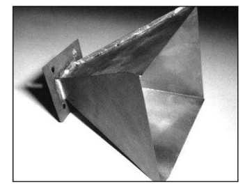
10GHz pyramidal horn antenna with approx. 18dBi visible gain like the picture below The first parameter in planning the antenna are the gain and maximum antenna size. These two things of course are related to each other, and can be estimated as follows.
L = H-plane length (λ) = 0.0654 × gain (Eq 1)
A = H-plane aperture (λ) = 0.0443 × gain (Eq 2)
B = E-plane aperture (λ) = 0.81 A (Eq 3)
Where :
Gain is expressed as a ratio, 20 dBi gain = 100 L, A and B are dimensions shown in Figure above. From the above equation for the dimensions of the antenna which has a gain 20dBi is a funnel that works in the 10.368GHz frequency. one length the band of 10.368GHz is 1.138 inches. Length (L) of the funnel is 0.0654 x 100 = 6.54 lambda. At 10.368GHz. Appropriate aperture for the H-plan (A) horn is 4.43 lamda or 5.04 inches, and the E-plan aperture is (B) 4.08 inches.
The easiest way to make such a horn antenna is to prepare the side pieces and solder them together. With Thus, the antenna material is made of metal that is easy to solder.

It is not recommended to use aluminum material, because it is difficult to manufacture. The dimensions of the triangular pieces are shown in Figure above.
Notice that the pieces of the triangle are trimmed at the ends of the which is tapered to fit the aperture of the waveguide (0.9 x 0.4 inch). This make the length
from the base to the apex of the small triangle ( side B) shorter compared to side (A). Also note that the length S of the two sides different funnels must be the
same in order to be assembled together. Need care must be taken in assembling this funnel antenna. The dimensions of the sides can be calculated by simple geometric math. But it will be easier if you make a pattern first on cardboard. From pattern cut and made an artificial funnel antenna first to make sure everything fits and can be assembled together before cutting sheets of antenna material such as brass or copper.
Cut 2 pieces of cardboard for side A and side B and glue them together , in the form of a funnel. After that prepare a new sheet and cut 5.04 x 4.08 inches and
punch a hole in the center to a size of 0.9 x 0.4 inches for the waveguide. If these dimensions are correct, use this cardboard pattern to mark or draw a pattern
on a sheet of antenna material that actually. Cut the sheet of brass/copper antenna material carefully, because cutting errors will be fatal and you will lose
antenna material because it must be wasted. The next step is to put the parts together side by soldering. Remember the soldering part is the outside connection.
Because if the part in the connection will affect its RF radiation and can reduce the gain of the funnel antenna.
reference :
No comments:
Post a Comment