

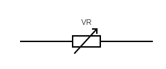
VARIABLE RESISTOR

POTENTIOMETER
.png)
.png)
THERMISTOR

.png)
LIGHT DIODE RESISTOR (LDR)

.png)
CAPACITOR (C)


.png)
TRIMMER CAPACITOR

.png)
POLARISED CAPACITOR

DIODE

ZENER DIODE


PHOTODIODE

SCHOTTKY DIODE

RAIL

GROUND AND EARTH
%20and%20Earth.png)
 |
| Ohm's Law Helper Diagram |
A potential difference of 1 volt will force a current of 1 Ampere through a resistance of 1 ohm, or :
V = I x R
I = V/R
R = V/I
P = I x V (or) I^2 x R
Resistor Networks are one of the most important and widely used building blocks in electronics. They appear in almost every electronic circuit, from simple voltage dividers to advanced digital-to-analog converters, microcontroller interfaces, radio frequency systems, and industrial control equipment.
A resistor network is not just a random collection of resistors. It is a carefully designed arrangement that allows engineers to control voltage, current, signal levels, impedance, and biasing with high precision. Understanding resistor networks is essential for students, hobbyists, technicians, and professional engineers.
In this comprehensive guide, we will explore what resistor networks are, how they work, the different types of resistor networks, their formulas, design considerations, real-world applications, and common mistakes to avoid.
Resistor networks are combinations of two or more resistors connected together in a specific configuration to achieve a desired electrical function. These resistors may be connected in series, parallel, or a mixture of both.
Instead of using individual resistors, engineers often use resistor networks to:
Resistor networks can be built using discrete resistors or manufactured as integrated resistor network packages (SIP, DIP, or surface-mount arrays).
Resistor networks simplify circuit design and improve reliability. Instead of calculating and placing many individual resistors, a properly designed resistor network ensures consistent performance, better tolerance matching, and reduced circuit complexity.
Key benefits of resistor networks include:
Calculate equivalent resistance for series or parallel resistor networks.
In a series resistor network, resistors are connected end-to-end so that the same current flows through each resistor.
Total resistance:
Rtotal = R1 + R2 + R3 + ...
Series resistor networks are commonly used in:
In a parallel resistor network, all resistors share the same voltage, but current divides among them.
Total resistance:
1 / Rtotal = 1 / R1 + 1 / R2 + 1 / R3 + ...
Parallel resistor networks are useful when:
Most real-world resistor networks are combinations of series and parallel connections. These networks allow designers to achieve precise resistance values that may not be available with standard resistor values.
Series-parallel resistor networks are common in:
One of the most common examples of resistor networks is the voltage divider. It consists of two or more resistors in series that divide an input voltage into smaller output voltages.
Voltage divider formula:
Vout = Vin × (R2 / (R1 + R2))
Voltage divider resistor networks are widely used in:
A ladder resistor network consists of repeating series and parallel resistor sections arranged in a ladder-like structure.
These resistor networks are used in:
Ladder resistor networks offer predictable voltage steps and excellent linearity when designed correctly.
The R-2R resistor network is one of the most famous resistor network configurations. It uses only two resistor values: R and 2R.
Despite its simplicity, the R-2R resistor network provides high accuracy and scalability, making it ideal for DAC applications.
Advantages of R-2R resistor networks:
Modern electronics often use integrated resistor networks packaged in:
These packages contain multiple resistors with matched tolerances, improving performance in precision applications.
Resistor networks are used for pull-up and pull-down resistors, voltage dividers, and analog input conditioning.
Audio mixers, attenuators, and filters rely heavily on resistor networks for signal shaping.
In power supplies, resistor networks provide feedback sensing, voltage scaling, and protection functions.
Resistor networks are used in impedance matching, biasing RF amplifiers, and signal sampling.
Ignoring these factors can lead to inaccurate measurements, unstable circuits, or component failure.
| Feature | Resistor Network | Individual Resistors |
|---|---|---|
| Accuracy | High (matched) | Moderate |
| PCB Space | Compact | Larger |
| Cost | Lower for multiple resistors | Higher assembly cost |
As electronics continue to miniaturize, resistor networks are becoming more integrated into ICs and system-on-chip designs. Advanced thin-film and laser-trimmed resistor networks are pushing accuracy and stability to new levels.
Resistor Networks are essential components in modern electronics. From simple voltage dividers to precision DACs and RF circuits, resistor networks provide reliable, scalable, and accurate solutions for controlling voltage and current.
By understanding resistor network types, calculations, and applications, you can design better, safer, and more efficient circuits. Whether you are a beginner or an experienced engineer, mastering resistor networks is a fundamental skill in electronics.
For accurate resistor networks, matched resistor arrays provide better stability and tolerance than individual resistors.

CIRCUIT DESCRIPTION


=* by Doug Demaw, W1FB *=
 |
| Principle of a directional antenna |
 |
| Cardiold shape radiation pattern |
What is a surge voltage ? How does it occur ?
Various types of surge voltages occur in electrical plants and electronic systems. They are differentiated mainly by their duration and power. Depending on the cause, a surge voltage can last a few hundred microseconds, hours or even days. The amplitude can range from a few millivolts to some ten thousand volts. The direct or indirect consequences of lightning strikes are one particular cause of surge voltages. Here, during the surge voltage, high surge currents with amplitudes of up to some ten thousand amperes can occur. In this case, the consequences are particularly serious. This is because the damaging effect first of all depends on the power of the respective surge voltage pulse.
The phenomenon of surge voltage
Every electrical device has a specific dielectric strength. If the level of a surge voltage exceeds this strength, malfunctions or damage can occur. Surge voltages in the high or kilovolt range are generally transient overvoltages of comparatively short duration. They generally last from a few hundred microseconds to a few milliseconds. As the maximum amplitude of such transients can amount to several kilovolts, steep voltage increases and differences are often the consequence. Surge protection is the only thing that helps. Indeed, the operator of an electrical system generally replaces the material damage to the system with corresponding protection. However, the difference in time between failure of the system to maintenance represents a risk in itself. This failure is often not covered by insurance and, within a short period of time, can become a heavy financial burden – especially in comparison to the cost of a lightning and surge protection concept.
This is how surge protection works

Surge protection should ensure that surge voltages cannot cause damage to installations, equipment or end devices. As such, surge protective devices (SPDs) chiefly fulfil two tasks: • Limit the surge voltage in terms of amplitude so that the dielectric strength of the device is not exceeded. • Discharge the surge currents associated with surge voltages. The way in which the surge protection works can be easily explained by means of the equipment's power supply diagram (Fig. 7). As described in Section 1.4, a surge voltage can arise either between the active conductors as normalmode voltage (Fig. 8) or between active conductors and the protective conductor or ground potential as common mode voltage (Fig. 9).

With this in mind, surge protective devices are installed either in parallel to the equipment, between the active conductors themselves (Fig. 10) or between the active conductors and the protective conductor (Fig. 11). A surge protective device functions in the same way as a switch that turns off the surge voltage for a brief time. By doing so, a sort of short circuit occurs; surge currents can flow to ground or to the supply network. The voltage difference is thereby restricted (Fig. 12 and 13). This short circuit of sorts only lasts for the duration of the surge voltage event, typically a few microseconds. The equipment to be protected is thereby safeguarded and continues to work unaffected.
Lightning and surge protection standards
National and international standards provide a guide to establishing a lightning and surge protection concept as well as the design of the individual protective devices. A distinction is made between the following protective measures: • Protective measures against lightning strike events: lightning protection standard IEC 62305 deals with this. A key component of this is an extensive risk assessment regarding the requirement, scope, and cost-effectiveness of a protection concept. • Protective measures against atmospheric influences or switching operations: IEC 60364-4-44 deals with this. In comparison with IEC 62305, it is based on a shortened risk analysis and uses this as the basis for deriving corresponding measures. In addition to the standards mentioned, if applicable, other legal and country- specific stipulations are also to be considered.
An antenna is defined by Webster‘s Dictionary as ―a usually metallic device (as a rod or wire) for radiating or receiving radio waves.‖ The IEEE Standard Definitions of Terms for Antennas (IEEE Std 145–1983) defines the antenna or aerial as ―a means for radiating or receiving radio waves.‖ In other words the antenna is the transitional structure between free-space and a guiding device. The guiding device or transmission line may take the form of a coaxial line or a hollow pipe (waveguide), and it is used to transport electromagnetic energy from the transmitting source to the antenna or from the antenna to the receiver. In the former case, we have a transmitting antenna and in the latter a receiving antenna.

Definition of antenna
An antenna can be defined in the following different ways:
1. An antenna may be a piece of conducting material in the form of a wire, rod or any other shape with excitation.
2. An antenna is a source or radiator of electromagnetic waves.
3. An antenna is a sensor of electromagnetic waves.
4. An antenna is a transducer.
5. An antenna is an impedance matching device.
6. An antenna is a coupler between a generator and space or vice-versa.
source : https://www.sathyabama.ac.in/sites/default/files/course-material/2020-10/SEC1301.pdf
Electromagnetic Radiation is energy in the form of a wave of oscillating electric and magnetic fields, the wave travels through a vacuum at a velocity of 2.998 x 10^8 meters per second (186,284 miles per second). The Wavelength of an electromagnetic wave determines its properties , x-rays , infrared , microwaves , radio waves and light are electromagnetic radiation.


There are various types of remote-control extenders. Many of them use an electrical or electromagnetic link to carry the signal from one room to the next. Here we use a fibre-optic cable. The advantage of this is that the thin fibre-optic cable is easier to hide than a 75-Q coaxial cable, for example. An optical link also does not generate any additional radiation or broadcast interference signals to the surroundings. We use Toslink modules for connecting the receiver to the transmitter. This is not the cheapest solution, but it does keep everything compact. You can use a few metres of inexpensive plastic fibreoptic cable, instead of standard optical cable for interconnecting digital audio equipment. The circuit has been tested using ten metres of inexpensive plastic fibre-optic cable between the receiver and the transmitter (which is described elsewhere in this issue).
The circuit is simplicity itself. A standard IR receiver/demodulator (IC1, an SFH506) directly drives the Toslink transmitter IC2. We have used the RC5 frequency of 36 kHz, but other standards and frequencies could also be used. Both ICs are well decoupled, in order to keep the interference to the receiver as low as possible. Since the Toslink transmitter draws a fairly large current (around 20 mA), a small mains adapter should be used as the power source. There is a small printed circuit board layout for this circuit, which includes a standard 5-V supply with reverse polarity protection (D2). LED Dl is the power-on indicator. The supply voltage may lie between 9 and 30 V. In the absence of an IR signal, the output of IC1 is always High, and the LED in IC2 is always on. This makes it easy for the transmitter unit to detect whether the receiver unit is switched on. The PCB shown here is unfortunately not available readymade through the Publishers' Readers Services.


source : https://archive.org/details/ElektorCircuitCollections20002014/page/n13/mode/2up?view=theater
This circuit restores the original modulation of the signal received from the remote-control unit, which was demodulated by the receiver unit at the other end of the extender (see 'Receiver for fibre-optic IR extender').
If no signal is received, the Toslink transmitter in the receiver is active, so a High level is present at the output of the Toslink receiver in this circuit. Buffer IC2a then indicates via LED Dl that the receiver unit is active. The received data are re-modulated using counter IC3, which is a 74HCT4040 since the Toslink module has a TTL output. In the idle state, IC3 is held continuously reset by IC1. The oscillator built around IC2c runs free. When the output of the Toslink receiver goes Low, the counter is allowed to count and a carrier frequency is generated. This frequency is determined by the oscillator frequency and the selected division factor. Here, as with the receiver, we assume the use of RC5 coding, so a combination has been chosen that yields exactly 36 kHz. The oscillator frequency is divided by 2 9 on pin 12 of the counter, and 18.432 MHz 2 9 = 36 kHz. The circuit board layout has a double row of contacts to allow various division factors to be selected, in order to make the circuit universal. You can thus select a suitable combination for other standards, possibly along with using a different crystal frequency. The selected output is connected to four inverters wired in parallel, which together deliver the drive current for the IR LEDs D3 and D4 (around 50 mA). A signal from the counter is also indicate that data are being transmitted, via LED D2. This has essentially the opposite function of LED Dl, which goes out when D2 is blinking. In the oscillator, capacitor C3 is used instead of the usual resistor to compensate for the delay in IC2c. As a rule, this capacitor is needed above 6 MHz. It should have the same value as C load of the crystal, or in other words 0.5C1 (where CI = C2). At lower frequencies, a lkQ to 2kQ2 resistor can be used in place of C3.
A yellow LED is used for the power-on indicator D5. The current through this LED is somewhat higher than that of the other LEDs. If you use a red high-efficiency LED instead, R5 can be increased to around 3kQ3.
The circuit draws approximately 41 mA in the idle state when the receiver is on. If the receiver is switched off, the transmitter emits light continuously, and the current consumption rises to around 67 mA.

The PCB shown here is unfortunately not available readymade through the Publishers' Readers Services.
source : https://archive.org/details/ElektorCircuitCollections20002014/page/n1/mode/2up?view=theater

In order to listen to your heartbeat you would normally use a listening tube or stethoscope. This circuit uses a piezo sounder from a musical greetings card or melody generator, as a microphone. This transducer has an output signal in the order of 100 mV and its low frequency response is governed by the input impedance of the amplifier. For this reason we have chosen to use an emitter follower transistor amplifier. This has a high input impedance and ensures that the transducer will have a very low frequency response. At the output you just need to connect a set of low impedance headphones to be able to listen to your heartbeat.
Replacing the emitter follower with a Darlington transistor configuration will further increase the input impedance of the amplifier.
source : https://archive.org/details/ElektorCircuitCollections20002014/page/n3/mode/2up?view=theater
It is fairly easy to produce professionally looking, permanent front panel foils ('decals') for use on electronic equipment if you have a PC available along with an inkjet printer ( or similar). Plus, of course, matt transparent sheet of the self-adhesive type as used, for instance, to protect book covers. This type of foil may be found in stationery shops or even the odd building market. One foil brand the author has used successfully goes by the name of Foglia Transparent. The production sequence is basically as follows:

1. The decal is designed at true size (1:1 or 100%) with a graphics program or a word processor, and then printed in black and white on a sheet of white paper (do not use the colour ink cartridge). Allow the ink to dry. Cut the foil as required, then pull the adhesive sheet from the paper carrier sheet. Keep the carrier paper handy, it will be used in the next phase.
2. Once the ink has dried, the transparent foil is placed on top of the decal. The foil is lightly pressed and then slowly pulled off the paper again (see photograph). Because the adhesive absorbs the ink to a certain extent, the mirror image of the decal artwork is transferred to the adhesive side of the foil.

3. For further processing, first secure the foil on the carrier paper again. Next, cut the decal to the exact size as required by the equipment front panel. Finally, pull off the carrier sheet again and apply the transparent foil on to the metal or plastic surface.
source : https://archive.org/details/ElektorCircuitCollections20002014/page/n13/mode/2up?view=theater