Antenna Handbook

Smith Chart Tool

The Smith Chart tool is a graphical calculator designed specifically for analyzing impedance and reflection coefficient in RF (Radio Frequency) circuits. It's a powerful visualization tool that helps engineers understand the relationship between these two crucial parameters.

Here's a breakdown of the Smith Chart tool:

  • Function: Visually represent impedance values and analyze how they impact signal transmission in RF circuits.
  • Appearance: A circular chart with two overlapping scales: resistance (horizontal) and reactance (vertical).
  • Applications: Primarily used for impedance matching, where the goal is to achieve optimal power transfer between a source and a load in an RF circuit.
  • Benefits: Offers a clear visual representation of complex calculations, aiding in analysis, design, and troubleshooting of RF circuits.
  • Examples of Use:
    • Finding the conjugate match (ideal impedance for perfect matching)
    • Determining the reflection coefficient based on the impedance value
    • Analyzing the impact of component changes on overall impedance
    • Visualizing resonant frequencies and reactance values in RF circuits

While the Smith Chart might seem complex at first, it's a valuable tool for anyone working with RF circuits. Imagine it as a map that helps you navigate the often-tricky world of impedance and signal transmission.

In the realm of radio frequency (RF) engineering, visualizing and analyzing the intricate relationship between impedance and reflection coefficient is paramount. Enter the Smith chart, a powerful graphical tool that has become an indispensable asset for RF professionals. This comprehensive guide delves into the world of the Smith chart tool, exploring its history, principles, applications, and practical usage, equipping you to navigate the electromagnetic maze with newfound confidence.

The Birth of a Legend: The History of the Smith Chart

The Smith chart owes its creation to Phillip Hagar Smith, a brilliant engineer at Bell Telephone Laboratories. In 1939, Smith devised this ingenious graphical representation to simplify the complex calculations involved in impedance matching, a crucial aspect of RF circuit design. (keyword: Smith chart history)

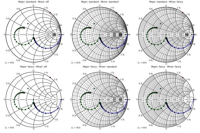
Demystifying the Smith Chart: A Visual Representation of Impedance

The Smith chart appears as a circular diagram with two overlapping scales:

  • Resistance (R) Scale: The horizontal axis represents the resistance component of an impedance (measured in ohms).
  • Reactance (X) Scale: The vertical axis represents the reactive component of an impedance (measured in ohms), which can be inductive (positive) or capacitive (negative).

Impedance values are plotted on the Smith chart as a single point. The location of this point depends on both the resistance and reactance values of the impedance. (keyword: Smith chart components)

Understanding the Magic Behind the Chart: Key Concepts

Several key concepts underpin the functionality of the Smith chart:

  • Constant Impedance Circles: Circles centered on the periphery of the chart represent constant resistance values. Moving inwards along a constant resistance circle signifies decreasing reactance.
  • Constant Reactance Circles: Circles centered on the chart with a zero resistance value represent constant reactance values. Moving outwards along a constant reactance circle signifies increasing resistance (for inductive reactance) or decreasing resistance (for capacitive reactance).
  • Smith Chart Coefficients: The chart incorporates markings for reflection coefficient (Γ), a crucial parameter in analyzing how much of a transmitted signal is reflected back due to impedance mismatch. (keyword: Smith chart concepts)

The Power of Visualization: Applications of the Smith Chart Tool

The Smith chart empowers RF professionals with a multitude of applications:

  • Impedance Matching: The primary application of the Smith chart involves visualizing and achieving optimal impedance matching between a source and a load in an RF circuit. A perfectly matched impedance results in maximum power transfer and minimal signal reflection. (keyword: Smith chart impedance matching)
  • Smith Chart Calculations: The chart facilitates calculations like finding the conjugate match (the ideal impedance for perfect matching) or determining the reflection coefficient based on the impedance value.
  • Smith Chart Analysis: RF engineers use the Smith chart to analyze the behavior of RF circuits, including identifying resonant frequencies, calculating reactance values, and visualizing the impact of component changes on the overall impedance.
  • Smith Chart Smith Chart Design: The chart can be used during the design phase of RF circuits to select appropriate components that achieve the desired impedance characteristics.

Utilizing the Smith Chart Tool: A Practical Guide

While the theoretical concepts underpinning the Smith chart might seem intimidating, practical usage becomes more intuitive with experience. Here's a basic guide to using the Smith chart tool:

  1. Identify Impedance Values: Determine the resistance and reactance values of the impedance you want to analyze.
  2. Locate the Point on the Chart: Plot the impedance value on the Smith chart by finding the intersection of the constant resistance circle corresponding to the resistance value and the constant reactance circle corresponding to the reactance value.
  3. Analyze and Interpret: Based on the location of the point on the chart, you can perform various analyses, such as determining the reflection coefficient or visualizing the impact of component changes on the impedance.

Smith Chart Tools in the Digital Age

While traditional paper Smith charts remain valuable, the digital age has brought forth a plethora of Smith chart software tools and online calculators. (keyword: Smith chart software) These tools offer several advantages:

  • Interactive Interface: They provide a user-friendly interface where you can input impedance values or manipulate components virtually to observe the real-time effects on the Smith chart.
  • Advanced Features: Some software offers advanced features like automatic calculations, annotations, and integration with circuit simulation tools.
  • Accessibility: Online Smith chart calculators offer a convenient way to perform quick analyses without requiring dedicated software installation.

The Future of the Smith Chart Tool

Despite the emergence of advanced simulation tools, the Smith chart remains a cornerstone of RF engineering due to its simplicity, visual clarity, and ability to provide a deeper understanding of impedance behavior. As RF technology continues to evolve, the Smith chart is likely to remain a valuable tool for generations of RF

Example Smith Chart Tool ::


Matplotlib extension for creating Smith charts with Python
pySmithPlot is a matplotlib extension providing a projection class for creating high quality Smith Charts with Python. The generated plots blend seamless into matplotlib's style and support almost the full range of customization options.


 Smith Chart extension for Chart.js . For more application with chart.js you can browse at chartjs.org
Simple Smith chart application serving as a paper.js demo


With this tool you can click and move the variable with your mouse. Click this link https://cemulate.github.io/smith-chart/

5. Smith-Chart-Software 

Windows Smith Chart software for RF circuit design. This software allows the user to perform interactive impedance transformation and matching on a Smith Chart. Please visit this blog for more information on the usage of the software.

Written in Visual Basic .NET. To compile:

  1. Create a new Visual Basic Windows Application project in Visual Studio (Version 2013 onwards).
  2. Add all the *.vb (visual basic code files) and *.resx (resource files) into the project.
  3. Build the project.
  4. Alternatively the pre-compile *.exe file is also included, which you can use immediately, for Windows 7 and above. Just copy to the harddisk and it should be able to run immediately. (source : Github.com)

6. Vue-Smith-Chart
Draw the Smith Chart in SVG with Vue.js , more about vue.js go to vuejs.org

more for free Smith Chart Tool you can browse on this repositories

Mastering Resistor Color Code Calculator and Chart—4 Band, 5 Band, or 6 Band Resistors

In the intricate world of electronics, resistors play a pivotal role, regulating current flow and shaping circuits. Understanding their values is paramount, and the resistor color code system simplifies this task. Whether you're a seasoned engineer or an enthusiastic hobbyist, mastering resistor color codes is essential. This comprehensive guide delves into the intricacies of resistor color codes, accompanied by handy calculators and charts to decipher them effortlessly.


Understanding Resistor Color Code:

Resistor color coding is a standardized method employed to denote the resistance value, tolerance, and sometimes reliability or temperature coefficient of resistors. This system assigns colors to digits and multipliers, which when decoded, reveal the resistance value in ohms. Additionally, color bands indicate tolerance levels, allowing for precise circuit design and troubleshooting.

The Basic Color Code System:

Traditionally, resistors feature four color bands, with each representing a specific digit or multiplier. The first two bands signify significant digits, the third represents the multiplier, and the fourth indicates tolerance. For instance, a resistor with color bands red, red, orange, and gold corresponds to a resistance value of 22 kΩ with a tolerance of ±5%.

Expanding to Five and Six Band Resistors:

To accommodate a wider range of values and tighter tolerances, five and six band resistor color coding systems were introduced. Five-band resistors add an additional significant digit, while six-band resistors include two additional significant digits. These enhancements enable precise resistance determination for specialized applications.

Utilizing Resistor Color Code Calculators:

While decoding resistor color bands manually is feasible, it's time-consuming and prone to errors. Enter resistor color code calculators—a boon for engineers and hobbyists alike. These online tools swiftly analyze color bands, providing accurate resistance values and tolerances within seconds. Let's take a look at an example:

Example of Resistor Color Code Calculator:

Imagine you have a resistor with color bands: yellow, violet, red, gold. Using a resistor color code calculator, input these colors, and voilà! The calculator swiftly reveals the resistor's resistance value as 47 kΩ with a tolerance of ±5%. This illustrates the efficiency and convenience offered by these calculators.

Resistor Color Code Chart:

In addition to calculators, reference charts are invaluable resources for decoding resistor color bands. These charts categorize color codes based on their corresponding values, facilitating quick identification and analysis. Below is a simplified version of a resistor color code chart:

courtesy Arrow.com


Three or four band resistors

The first two bands always denote the first two digits of the resistance value in ohms. On a three or four-band resistor, the third band represents the multiplier. 
This multiplier will basically shift your decimal place around to change your value from mega ohms to milliohms and anywhere in between. The fourth color band
 signifies tolerance. Keep in mind that if this band is absent and you are looking at a three-band resistor, the default tolerance is ±20%.

Five or six band resistors

Resistors with high precision have an extra color band to indicate a third significant digit. If your resistor has five or six color bands, the third band becomes this
 additional digit along with bands one and two. Everything else shifts to the right, making the fourth color band the multiplier and the fifth band the tolerance. 

A six-band resistor is basically a five-band type with an additional ring indicating the reliability, or the temperature coefficient (ppm/K) specification. 

Using brown, the most common sixth band color, as an example, every temperature change of 10°C changes the resistance value by 0.1%.

This Link Lists from Github will bring you to Resistor Color Code Calculator, you can choose for 3 Bands, 4 Bands, 5 Bands, 6 Bands

A tiny web app made in Svelte and Vite that decodes your resistors.
3 Bands Resistor Color Code Calculator


4 Bands Resistor Color Code Calculator 


5 Bands Resistor Color Code Calculator 


6 Bands Resistor Color Code Calculator 


2.  resistor-calculator color code 
Web app that calculates the resistance provided by a resistor based on the coloured 4 until 6 bands on the resistor body.
Go here to try it out.

4 Bands Resistor Color Code Calculator 


5 Bands Resistor Color Code Calculator 


6 Bands Resistor Color Code Calculator 


Link for Resistor Calculator https://gestalte.github.io/resistor-calculator/


React-based web app that lets you inventory your resistors by reading their color codes. This project is alternative to the classic to-do app . You can see the demo here: https://jhordyess.github.io/resistor-tracker/

Resistor Tracker Color Code Calculator 


    You can see the demo here: https://jhordyess.github.io/resistor-color-code/


Standard Resistors, 1%, 5%, and 10%

Standard resistors are fundamental components in electronic circuits, providing precise resistance values to control the flow of electric current. They are categorized based on their tolerance, which indicates the permissible deviation from their nominal resistance value. Resistors with a tolerance of 1%, 5%, and 10% are commonly used in electronic applications.

1% Tolerance Resistors:
These resistors are highly precise, with a tolerance of ±1% from their specified resistance value. They are suitable for applications where tight accuracy and stability are required, such as in precision instruments, measurement devices, and high-performance electronic circuits. 1% tolerance resistors offer consistent and reliable performance, ensuring minimal deviation from the desired resistance value.

5% Tolerance Resistors:
Resistors with a tolerance of 5% are widely used in general-purpose electronic circuits and consumer electronics. While they offer sufficient accuracy for many applications, they may exhibit slightly larger deviations from their nominal resistance values compared to 1% tolerance resistors. However, they are cost-effective and readily available, making them suitable for a wide range of applications where precision requirements are not critical.

10% Tolerance Resistors:
With a tolerance of ±10%, these resistors have the widest permissible deviation from their nominal resistance values. They are commonly used in low-precision applications, such as voltage dividers, current limiting circuits, and basic electronic projects where precision requirements are relatively lenient. Despite their lower accuracy, 10% tolerance resistors are economical and suitable for hobbyist projects and educational purposes.


Graphical Resistor Calculator (4 Band)

Graphical Resistor Calculator

Graphical Resistor Calculator is a Free Software to easily calculate the resistance of registers from the band colors.

Simply change the values from the dropdown menus.

Band 1Band 2Band 3Band 4
Value 1 (MSV)Value 2WeightTolerance
   

Resistance:  

1,000 Ω ±5%

Graphical Resistor Calculator Reference Chart

Standard Table For Calculating 4 Band Resistors' Resistance.

ColorDigit valueMultiplierMultiplied OutTolerance
Black01001
Brown110110
Red2102100
Orange31031,000
Yellow410410000
Green5105100,000
Blue61061,000,000
Violet710710,000,000
Gray8108100,000,000
White91091,000,000,000
Gold±5%
Silver±10%

How to read resistor color code ?

In the intricate world of electronics, resistors play a pivotal role, regulating current flow and shaping circuits. Understanding their values is paramount, and the resistor color code system simplifies this task. Whether you're a seasoned engineer or an enthusiastic hobbyist, mastering resistor color codes is essential. This comprehensive guide delves into the intricacies of resistor color codes, accompanied by handy calculators and charts to decipher them effortlessly.

Understanding Resistor Color Code:

Resistor color coding is a standardized method employed to denote the resistance value, tolerance, and sometimes reliability or temperature coefficient of resistors. This system assigns colors to digits and multipliers, which when decoded, reveal the resistance value in ohms. Additionally, color bands indicate tolerance levels, allowing for precise circuit design and troubleshooting.

The Basic Color Code System:

Traditionally, resistors feature four color bands, with each representing a specific digit or multiplier. The first two bands signify significant digits, the third represents the multiplier, and the fourth indicates tolerance. For instance, a resistor with color bands red, red, orange, and gold corresponds to a resistance value of 22 kΩ with a tolerance of ±5%.

Expanding to Five and Six Band Resistors:
To accommodate a wider range of values and tighter tolerances, five and six band resistor color coding systems were introduced. Five-band resistors add an additional significant digit, while six-band resistors include two additional significant digits. These enhancements enable precise resistance determination for specialized applications.

Utilizing Resistor Color Code Calculators:

While decoding resistor color bands manually is feasible, it's time-consuming and prone to errors. Enter resistor color code calculators—a boon for engineers and hobbyists alike. These online tools swiftly analyze color bands, providing accurate resistance values and tolerances within seconds. Let's take a look at an example:

Example of Resistor Color Code Calculator:

Imagine you have a resistor with color bands: yellow, violet, red, gold. Using a resistor color code calculator, input these colors, and voilà! The calculator swiftly reveals the resistor's resistance value as 47 kΩ with a tolerance of ±5%. This illustrates the efficiency and convenience offered by these calculators.

Resistor Color Code Chart:

In addition to calculators, reference charts are invaluable resources for decoding resistor color bands. These charts categorize color codes based on their corresponding values, facilitating quick identification and analysis. Below is a simplified version of a resistor color code chart:

courtesy Arrow.com


Three or four band resistors

The first two bands always denote the first two digits of the resistance value in ohms. On a three or four-band resistor, the third band represents the multiplier. 
This multiplier will basically shift your decimal place around to change your value from mega ohms to milliohms and anywhere in between. The fourth color band
 signifies tolerance. Keep in mind that if this band is absent and you are looking at a three-band resistor, the default tolerance is ±20%.

Five or six band resistors

Resistors with high precision have an extra color band to indicate a third significant digit. If your resistor has five or six color bands, the third band becomes this
 additional digit along with bands one and two. Everything else shifts to the right, making the fourth color band the multiplier and the fifth band the tolerance. 
A six-band resistor is basically a five-band type with an additional ring indicating the reliability, or the temperature coefficient (ppm/K) specification. 
Using brown, the most common sixth band color, as an example, every temperature change of 10°C changes the resistance value by 0.1%.