Two problems seem to insinuate themselves into the process. First, the Zepp feed is a bit cumbersome (not everyone is enamored of parallel transmission line). Second, how do you go about actually grounding that termination resistor? If it is above ground, then the wire to ground is long, and definitely not at ground potential for RF. If you want to avoid both the straight Zepp feed system employed by most such antennas, as well as the resistor-grounding problem, then you might want to consider the counterpoise longwire antennas shown in Fig. 6-25.
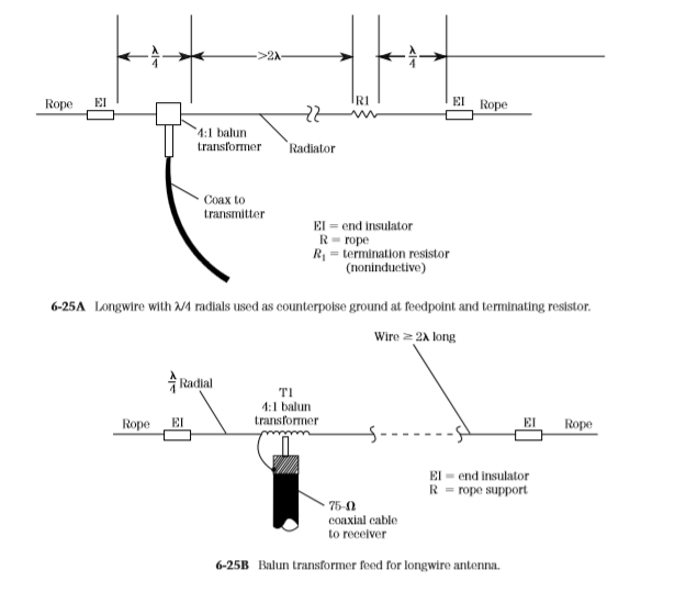
One counterpoise is at the feedpoint, where it connects to the “cold” side of the transmission line. The parallel line is then routed to an antenna tuning unit (ATU), and from there to the transmitter. The other counterpoise is from the cold end of the termination resistor to the support insulator. This second counterpoise makes it possible to eliminate the earth ground connection, and all the problems that it might entail, especially in the higher end of the HF spectrum, where the wire to ground is of substantial length compared with 1λ of the operating frequency.
A slightly different scheme used to adapt the antenna to coaxial cable is shown in Fig. 6-25B. In this case, the longwire is a resonant type (nonterminated). Normally, one would expect to find this antenna fed with 450-Ω parallel transmission line. But with a λ/4 radial acting as a counterpoise, a 4:1 balun transformer can be used to effect a reasonable match to 75-Ω coaxial cable. The radial is connected to the side of the balun that is also connected to the coaxial cable shield, and the other side of the balun is connected to the radiator element.
From The Book " Practical Antenna Handbook - Joseph P. Carr"
No comments:
Post a Comment