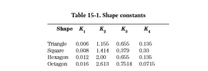
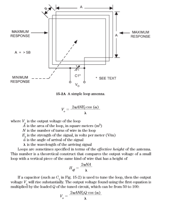
A wire loop antenna is made by winding a large coil of wire, consisting of one or more turns, on some sort of frame. The shape of the loop can be circular, square, triangular, hexagonal, or octagonal. For practical reasons, the square loop seems to be most popular. With one exception, the loops considered in this section will be square, so you can easily duplicate them. The basic form of the simplest loop is shown in Fig. 15-2. This loop is square, with sides the same length A all around. The width of the loop (B) is the distance from the first turn to the last turn in the loop, or the diameter of the wire if only one turn is used. The turns of the loop in Fig. 15-2 are depth wound, meaning that each turn of the loop is spaced in a slightly different parallel plane. The turns are spaced evenly across distance B. Alternatively, the loop can be wound such that the turns are in the same plane (this is called planar winding). In either case, the sides of the loop (A) should be not less than five times the width (B). There seems to be little difference between depth- and planar-wound loops. The far-field patterns of the different shape loops are nearly the same if the respective cross-sectional areas ( r2 for circular loops and A2 for square loops) are less than 2/100. The reason why a small loop has a null when its broadest aspect is facing the signal is simple, even though it seems counterintuitive at first blush. Take a look at Fig. 15-3. Here, we have two identical small loop antennas at right angles to each other. Antenna A is in line with the advancing radio wave, whereas antenna B is broadside to the wave. Each line in the wave represents a line where the signal strength is the same, i.e., an “isopotential line.” When the loop is in line with the signal (antenna A), there is a difference of potential from one end of the loop to the other, so current can be induced in the wires. When the loop is turned broadside, however, all points on the loop are on the same potential line, so there is no difference of potential between segments of the conductor. Thus little signal is picked up (and the antenna therefore sees a null). The actual voltage across the output terminals of an untuned loop is a function of the angle of arrival of the signal (Fig. 15-4), as well as the strength of the signal and the design of the loop. The voltage Vo is given by


Even though the output signal voltage of tuned loops is higher than that of untuned loops, it is nonetheless low compared with other forms of antenna. As a result, a loop preamplifier usually is needed for best performance.

No comments:
Post a Comment