I found that a 15-turn main loop resonated in the AM BCB with a standard 365-pF capacitor, but the two-turn coupling loop required three sections of a ganged 3 365-pF capacitor connected in parallel to resonate at the same frequencies. In several experiments, I used computer ribbon cable to make the loop turns. This type of cable consists of anywhere from 8 to 64 parallel insulated conductors arranged in a flat ribbon shape. Properly interconnected, the conductors of the ribbon cable form a continuous loop. It is no problem to take the outermost one or two conductors on one side of the wire array and use them for a coupling loop.
Transformer Loop Antenna
It is common practice to make a small loop antenna with two loops rather than just one. Figure 15-5 shows such a transformer loop antenna. The main loop is built exactly as discussed above: several turns of wire on a large frame, with a tuning capacitor to resonate it to the frequency of choice. The other loop is a one- or two-turn coupling loop.This loop is installed in very close proximity to the main loop, usually (but not necessarily) on the inside edge not more than a couple of centimeters away. The purpose of this loop is to couple signal induced from the main loop to the receiver at a more reasonable impedance match. The coupling loop is usually untuned, but in some designs a tuning capacitor (C2) is placed in series with the coupling loop. Because there are many fewer turns on the coupling loop than on the main loop, its inductance is considerably smaller. As a result, the capacitance to resonate is usually much larger. In several loop antennas constructed for purposes of researching this chapter,
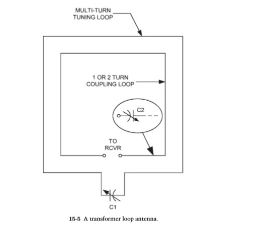
I found that a 15-turn main loop resonated in the AM BCB with a standard 365-pF capacitor, but the two-turn coupling loop required three sections of a ganged 3 365-pF capacitor connected in parallel to resonate at the same frequencies. In several experiments, I used computer ribbon cable to make the loop turns. This type of cable consists of anywhere from 8 to 64 parallel insulated conductors arranged in a flat ribbon shape. Properly interconnected, the conductors of the ribbon cable form a continuous loop. It is no problem to take the outermost one or two conductors on one side of the wire array and use them for a coupling loop.
I found that a 15-turn main loop resonated in the AM BCB with a standard 365-pF capacitor, but the two-turn coupling loop required three sections of a ganged 3 365-pF capacitor connected in parallel to resonate at the same frequencies. In several experiments, I used computer ribbon cable to make the loop turns. This type of cable consists of anywhere from 8 to 64 parallel insulated conductors arranged in a flat ribbon shape. Properly interconnected, the conductors of the ribbon cable form a continuous loop. It is no problem to take the outermost one or two conductors on one side of the wire array and use them for a coupling loop.
Subscribe to:
Post Comments (Atom)
No comments:
Post a Comment