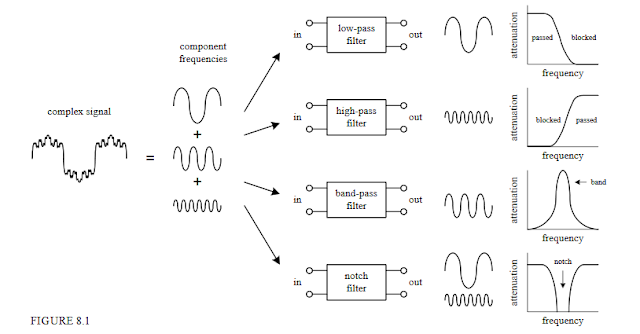
A filter is a circuit that is capable of passing a specific range of frequencies while block-ing other frequencies. The four major types of filters include low-pass filters, high-pass filters, bandpass filters,and notch filters(or band-reject filters). A low-pass filter passes low-frequency components of an input signal, while a high-pass filter passes high-frequency components. A bandpass filter passes a narrow range of frequencies centered around the filter’s resonant frequency, while a notch filter passes all frequencies except those within a narrow band centered around the filter’s resonant frequency
 Filters have many practical applications in electronics. For example, within a dc power supply, filters can be used to eliminate unwanted high-frequency noise present within the ac line voltage, and they act to flatten out pulsing dc voltages generated by the supply’s rectifier section.
In radio communications, filters make it possible for a radio receiver to provide the listener with only the desired signal while rejecting all others.
Likewise, filters allow a radio transmitter to generate only one signal while attenuating other signals that might interfere with different radio transmitters’ signals.
In audio electronics, filter networks called crossover networks are usedt o divert low audio signals to woofers, middle-range frequencies to mid range speakers, and high frequencies to tweeters.
The list of filter applications is extensive.There are two filter types covered in this chapter, namely, passive filter sand active filters.
Passive filters are designed using passive elements (e.g., resistors, capacitors,and inductors) and are most responsive to frequencies between around 100 Hz and 300 MHz.
The lower frequency limit results from the fact that at low frequencies the capacitance and inductance values become exceedingly large, meaning prohibitively large components are needed.
The upper frequency limit results from the fact that at high frequencies parasitic capacitances and inductances wreak havoc.)
When designing passive filters with very steep attenuation falloff responses, the number of inductor and capacitor sections increases.
As more sections are added to get the desired response, the greater is the chance for signal loss to occur. Also, source and load impedances must be taken into consideration when designing passive filters.
Active filters, unlike passive filters, are constructed from op amps, resistors, and capacitors—no inductors are needed. Active filters are capable of handling very low frequency signals (approaching 0 Hz), and they can provide voltage gain if needed(unlike passive filters).
Active filters can be designed to offer comparable performance to LC filters, and they are typically easier to make, less finicky, and can be designed without the need for large-sized components.
Also, with active filters, a desired input and output impedance can be provided that is independent of frequency. One major drawback with active filters is a relatively limited high-frequency range.
Above around 100 kHz or so, active filters can become unreliable (a result ofthe op amp’s bandwidth and slew-rate requirements).
At radio frequencies, it is best to use a passive filter
(from Book : Practical Electronics for Inventors by : Paul Scherz)
No comments:
Post a Comment