Antenna Handbook | Best Antennas, Free Calculators & Top Antenna Deals

World Band Radio Antenna

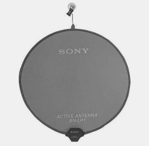
  • *The AN-LP1 is not recommended for use with Sony models ICF-SW10, ICF-SW11, ICF-SW77.
  • *The AN-LP1 derives power from the radio when connected to Sony models ICF-SW1000T and ICF-SW7600G.
  • http://www.amazon.com/gp/product/B00009VT84/ref=as_li_qf_sp_asin_il_tl?ie=UTF8&camp=1789&creative=9325&creativeASIN=B00009VT84&linkCode=as2&tag=1ststroller-20&linkId=DUIQEHTEBEG4GWEF
The Sony AN-LP1 portable active antenna is just right for travelers who wants maximum performance from their world band radio. The flexible folding loop antenna is 19 inches (48 cm) when open, but folds down with a twist to a mere 7 inches (18 cm) and neatly fits in the supplied soft carrying case. A mounting clip and suction cup on the end of the loop allows easy placement in a variety of situations. The suction cup is especially useful for mounting the antenna to a window where reception will often be the best. A reselection knob selects operation from 3.85-21.95 MHz. The AN-LP1 requires two AA cells for about 40 hours of use. The supplied cable connecting the loop to the ANl-LP1 control box is 12 feet long. The supplied cable connecting the control box to the radio is 8 inches long. Output is to a 3.5 mm mini plug. Comes with an English, French, German and Japanese instructions from Sony. Item is made in Japan.

25 mW Digital FM Transmitter Kit

  • PLL synthesized for drift free operation
  • Front panel digital control and display of all settings and parameters
  • Professional metal case for noise-free operation
  • EMI filtering on audio and power inputs
  • Electronic Kit, Assembly Required


    http://www.amazon.com/gp/product/B00076L4IO/ref=as_li_qf_sp_asin_il_tl?ie=UTF8&camp=1789&creative=9325&creativeASIN=B00076L4IO&linkCode=as2&tag=1ststroller-20&linkId=DPCMJHPWLKBT3DL2
  • THE LEGACY CONTINUES! For nearly a decade we have been the leader in hobbyist FM radio transmitters. First we came out with our low cost FM10, the tunable FM transmitter that has set records as the most popular school, scouting, and first time hobbyist kit. Then we introduced the world famous FM25 series of FM transmitters. We took the basic concept of the tunable FM10, made it synthesized for rock solid and stable operation and gave it the features and performance that made it THE LEADER in low cost FM stereo transmitters. From there we introduced our FM100 series Super Pro FM Stereo Radio Station. We took the exceptional circuitry of the FM25 and built a stand-alone "radio station" around it, complete with microphone and line level audio mixers, digital control and display of operating frequency, higher RF power output options, and put it all in a professional case. To date, the FM100 series continue to be our #1 selling products! How could we make history better? We listened to thousands of our customers that loved the stability of the PLL synthesized FM25 series but wanted easy to change front panel control of the operating frequency and wanted to know what frequency they were transmitting on. They also wanted the capability of controlling the audio levels at the transmitter rather than changing the input levels. We thought those were very legitimate requests, and our response was to move up to the FM100 series. "But I don't need an audio mixer, I don't need all that fancy stuff built-in, I just need a small transmitter I can afford"! Here you go, designed from the ground up...the FM30 series! The FM30 is designed using through-hole technology and components and is available only as a do-it-yourself kit, with a 25mW output very similar to our FM25 series.

AM FM Radio Kit, Good for Educational

http://www.amazon.com/gp/product/B008515U1U/ref=as_li_qf_sp_asin_il_tl?ie=UTF8&camp=1789&creative=9325&creativeASIN=B008515U1U&linkCode=as2&tag=1ststroller-20&linkId=XNWWFFVYHWNM75U2This Kit AM FM Radio, good for educational purposed for building AM FM Radio and for knowing more AM FM radio receiver . 

This Kit come with books as a guide for study more about the AM FM circuit, start from Audio Amplifier, AM Detector, AM IF, AM Amplifier, AM Mixer & Oscillator, FM Detector, 1st FM IF, 2nd FM IF, and FM RF Stages. Superheterodyne receiver of standard AM and FM broadcast frequencies.


http://www.amazon.com/gp/product/B008515U1U/ref=as_li_qf_sp_asin_il_tl?ie=UTF8&camp=1789&creative=9325&creativeASIN=B008515U1U&linkCode=as2&tag=1ststroller-20&linkId=XNWWFFVYHWNM75U2


  • AM/FM Radio Kit (Combo IC & Transistor)
  • Includes 64 page educational training guide
  • with multiple choice questions and answers
  • Training course of 56 pages is divided into 9 lessons: Audio Amplifier, AM Detector, AM IF, AM Amplifier, AM Mixer & Oscillator, FM Detector, 1st FM IF, 2nd FM IF, and FM RF Stages. Superheterodyne receiver of standard AM and FM broadcast frequencies. Makes an excellent classroom project. Requires 9V battery, not included.

FM Radio Kit with Auto Scan Frequency

This Kit FM Radio Using IC as FM Tuner and IC for Amplifier. This FM Radio Kit scan FM frequency in 88-108 MHz and using auto scan  for scans up and for reset.

http://www.amazon.com/gp/product/B004YHZE0G/ref=as_li_qf_sp_asin_il_tl?ie=UTF8&camp=1789&creative=9325&creativeASIN=B004YHZE0G&linkCode=as2&tag=1ststroller-20&linkId=WEUQR44DCPV7SNIH
  • Build this kit to assemble a monophonic FM receiver (88-108mhz) with electronic auto-scan
  • Will help you understand the basics of working with printed circuit boards
  • Become familiar with a variety of electronic components
  • Develop good soldering skills
  • For 30 years Elenco has been using their strong engineering and design skills to develop reliable, affordable electronic test equipment, tools, and educational kits

    This kit is a monophonic FM (frequency modulation) receiver designed to receive FM signals in the frequency range (88-108mhz) it uses electronic auto-scan to search for FM stations. This scan system is done with two button switches-one switch scans up, the other resets to the start of the tuning position.

1byone® Window Antenna 50 Miles Super Thin HDTV Antenna with 20ft Coaxial Cable, Extreme Soft Design and Lightweight

  • FREE FOR LIFE - Never Pay Your Cable or Satellite For Television Again! 1byone antenna can pull in all of your local news, weather, sitcoms, kids and sports programming with NO monthly contract or bills. Just plug it in and connect to your television and let the antenna do all the work.
  • WINDOW ANTENNA - This 1byone window antenna is specially designed to match your window decoration. With its crystal transparent look and grace strips, it looks like a gorgeous art designed for your window.
  • DETACHABLE AMPLIFIER - A detachable amplifier and USB power adapter give you a better choice. If your tv picture is not crystal clear, or you can not get the weak signals from far away towers, you can use this amplifier to boost the weak signals. Remove the amplifier/booster if your house is very close to the broadcast tower with strong signals. A booster will cause self-oscillate and you may get fewer signals than without.
  • FULL HD, LONGER RANGE - 50 miles range to access from broadcast tower. It delivers full 1080p HD to any digital-ready TV. Comes with a 20-foot coaxial cable for greater flexibility. Makes it easier for you to place it in your house to get the best reception, especially for customers whose televisions are quite far away from windows.
  • BUYER GUARANTEE - We stand behind our antenna 100% with one year warranty. Please Note: Freeview reception is dependent upon environmental factors, we cannot guarantee reception in all conditions. We do offer a 30 day money back guarantee on all new items in order for you to test the suitability in your area.
Amplifier 

Installation Diagram of HDTV Antenna

 Installation HDTV Antenna on Windows, simple and aesthetic

Antenna Installation 


Antenna Pattern and Model

Super Thin HDTV Antenna with Detachable Amplifier Signal Booster for the Highest Performance the Longest Reception Range, 10ft Coax Cable, Bigger Flat Size Gets the Larger Reception Range

  • FREE FOR LIFE - Never Pay Your Cable or Satellite For Television Again! You Can Get All Local Crystal Clear Channels Absolutely Free! 1byone antenna can pull in all of your local news, weather, sitcoms, kids and sports programming with NO monthly contract or bills. Just plug it in and connect to your television and let the antenna do all the work.
  • DETACHABLE AMPLIFIER KIT - Attach the amplifier kit and boost 15 miles range! TV reception may vary depending on your local surroundings. If you get fewer channels, remove the amplifier kit. (Note: the amplifier may cause self-oscillate if your house is super close to the broadcast tower.) The detachable amplifier kit gives you two options!
  • HIGHER QUALITY - This 1byone HDTV Antenna will be the LAST antenna you will need to buy! If you have ever purchased other brand antennas, you will find out that 1byone antenna definitely is higher quality! There are so many hdtv antennas on the market at around $15, but some of the antennas are made of inferior materials, which can't stand moisture weather or exposed to sunshine. Buy 1byone tv antenna, you will get the real thing. You'll find out it's worth each dime you spent!
  • LONGER CABLE, EASIER SETUP - a longer cable makes it easier for you to place it at the best position in your house to get the best reception, especially for customers whose televisions are quite far away from windows. 1byone has very detailed setup instructions coming with the package. You also can get to Customers Service for help. Buy 1byone antenna; get rid of any setup problems.
  • BUYER GUARANTEE - We stand behind our antenna 100% with one year warranty. Please Note: Freeview reception is dependent upon environmental factors, we cannot guarantee reception in all conditions. We do offer a 30 day money back guarantee on all new items in order for you to test the suitability in your area.


Antenna Setup for Crystal Radio


Antenna for Crystal Radio can be setup in backyard or tall building, as high as possible , you can pick up much radio signal.


  Recommended Product Antenna :
This is Tune Trapper Marine Antenna for Boat, also suitable for Fiberglass boat Car, RV, where ground plane no exist. You can install it in any place that suitable, no power need, no ground, no amplifier need. Made in USA and water resistant. Have Tested, have good reception in AM/FM Band. Just plug in to your antenna connection in your radio and Tune to FM 87.5 MHz-108 MHz.
This Tune Trapper is 1/2 Wave Helical Dipole
For Marine used, this antenna is sealed housing by PVC for defend from harsh marine use.This Tune Trapper dimension is 24 inch long and 1/2 inch diameter, complete with 6 feet 95% copper wire with standard motorolla connector, is USA handmade. Performance is guaranteed, and this Tune Trapper in bench tested, for make sure crystal clear reception.

Radio Crystal With One Transistor 2SB178


This Circuit is simple with One NPN Transistor 2SB178, Signal
 selected from LC circuit and pick up with Germanium
 Diode IN34A or IN60 or OA70 and Amplified with Transistor 2SB178 and with Earphone or Headphone with Resistant about 8-2000 Ohm.

The component list

COMPONENT '60 Turns' = L
COMPONENT '500 pF' = CV
COMPONENT 'IN34A/IN60/OA70' = D
COMPONENT '10 nF' = C
COMPONENT '5K6' = R
COMPONENT '2SB178' = TN
COMPONENT '4K7' = R
COMPONENT 'Earphone 8 - 2000 Ohm' = SPKR
COMPONENT '100uF' = CE
COMPONENT 'SWITCH' = SWITCH
COMPONENT '1.5V' = BATTERY
COMPONENT '' = GND

Straight Radio or Crystal Radio


OA70 / IN34 / IN60 is Germanium Radio, choose only one type. Antenna high from Ground is high is possible, ground is a must to Steel Water pipe, or making one from a piece of copper approximately 1 meter down to the ground, so will be voltage between ground and radio wave pick up by antenna.

I have build this Radio and connected input speaker to line input notebook and running with Open Lab software and can pick up Radio Signal from about 6 km air distance.

====+  Parts List for   +====

10 nF                              1   Capacitor
VC 500 pF                     1   Variable Capacitor
OA70/IN34/IN60          1   D
GND                              1   GND
108 Turns,12 Turns        L Tap between 108 Turns and 12 Turns
8-2000 Ohm                  1   SPKR or Earphone 8 - 2000 Ohms


This is one of Product of Crystal Radio Kit with Mineral Gateway as Diode and without Battery, this crystal radio specification :

  • Conduct a radio wave experiment
  • Capture AM broadcasting radio waves
  • Works without the need of a battery
  • Science guide included (68 color pages)
  • Another fun, educational product from the company that brings you Snap Circuits


VLF and ELF Experiment Using Cable TV Antenna

This is simple experiment using Cable TV Antenna , Diode Germanium IN60 and Spectrum Lab Software free download.

Install Spectrum Lab on your computer and connect The Antenna to Diode Germanium IN60 and connect it to your PC/Laptop Micrphone Input. Connect The Ground and Antenna cable to Ground of Microphone Input and you will here some of Local Radio about ....km or ..miles with some noise background.

Warning : Do not try this in the Rainy Days with Lightning come up, It can harms you

The result are :


Electrochemical Liquid Vortexing Ionization System

This article is nothing to do with antenna system, but because I like to share everything what have been my interest. I will shared to everybody. This article is proved experiment from it's original at http://www.the-elvis.info , Kaialoha foundation, implement and tested cheap device that saving your fuel with low cost and reduce the CO emission to the air.


The writer pleased everybody to share his knowledge, you can copied this article and write it,make it,commercial it,all he ask you only tell his website on your page, like I do.

It is very simple device, all you need is a copper wire, aluminium wire or aluminium from coke,zinc or stainless steel wire,plastic inline fuel filter, and aluminium or stainless steel mesh and neodymium rare earth magnet ( more powerful than ordinary magnet, you can find it from old hard drive or you can experiment with magnet from old speaker).


How to make the recipe ?

Mixed 1/2 teaspoon of copper wire, aluminium wire,and zinc galvanized or stainless steel and break up the neodymium magnet mixed it.
You can find copper wire from old transformator,or old electric motor, and for aluminium you can use from coke can, for stainless steel you can use from coin or spoon or you can buy stainless steel wire,and neodymium magnet you can find it from old hard drive.
This is only my suggestion,maybe you have better ideas for find the ingredients for this project.

My Ilustration of this device :


The Installation :

  On his experiment,this device proved can reduce or saving the use of gasoline or diesel,and also reduce the CO Emission to the air. Last, I will post my experiment with this device on my diesel car to you.

E.L.V.I.S. recipe
How to make your own E.L.V.I.S.
Personal model.

Ingredients:

Copper shot
Aluminum shot
Zinc or Stainless steel shot
Ordinary plastic inline fuel filter
small piece of aluminum or stainless steel mesh

Optional

fancy metal screw type cleanable fuel filter
small Neodymium (rare earth) magnet
Small pice of aluminum

Recipe

Make 1/2 tsp of copper, aluminum, zinc (or stainless steel) shot by cutting approx.1/8 inch pieces of approx. 1/8 inch thick wire. For zinc use ordinary galvanized chainlink fence type wire.

Buy an ordinary economy plastic fuel filter intended for the engine you have in mind. Or use a more expensive metal screw open replacable/cleanable type.

Insert all the shot one by one into the filter through the intake tube. Tap it all down into the canister.

Optional: Break up a neodymium (rare earth) magnet small enough to insert a small piece in with the beads.

Either of the following

1) Cut a small unpainted piece of aluminum from a beer can to 1/4 inch long and wide as the inside diameter of output tube. make a longitudinal 1/2 twist in it (like a barber pole). Insert tightly into output tube so that no bead can get through. (test this)

2) Cut a 1/4 inch x 1/2 inch approx piece of stainless steel or aluminum mesh with holes smaller than 1/8 inch. Roll or fold it and insert into output tube so as to prevent beads from coming through. Test this.

Installation

Install like an ordinary extra fuel filter observing the direction arrows - input tube toward fuel tank, output tube toward fuel pump/carburetor. Must be located after the normal fuel filter and before the fuel pump/carburetor. Your normal filter now prefilters the fuel prolonging the life of the E.L.V.I.S. by slowing down clog up. Use extra fuel hose as needed but locate E.L.V.I.S. as close to fuel pump/carburetor as possible and stabilize it in some manner in a level position away from heat sources.

E.L.V.I.S. will work forever and never wear out. However. Since the EL Cheapo version above uses a paper element filter, it will eventually clog up even with another filter prefiltering the fuel. This will probably take years (if you change the prefilter at recommended intervals). When it eventually clogs up...well you'll have to pass up another Starbucks latte :-) Those who want to avoid this can use a fancy metal screwtype filter and replace the filter element with the beads. No clogging problem ever.

Commercial model.

Same recipe and ingredients as the personal model but with the following modifications. Big trucks, buses, construction machines usually use a large canister type fuel filter with hydraulic type lines and fittings.

The cheapest method:

Fill the element canister 1/2 to 2/3 with shot/magnet so the reservoir is ionized and then sucked through the filter.

The expensive method:

Install another fuel filter canister made as above. This involves extra lines and fittings that have to be made by qualified hydraulic mechanics. This is not expensive as the components are stock.

Good for all engines, marine/autos/pickups, gas or diesel. Not LPG...

Tested Result :


Original article (sources) : http://www.the-elvis.info

Disclaimer :
I am not tested yet this experiment/device , any impact occur will be your own responsibility 
this article based on literarture

Free electricity from Air

Free Electricity from Air Using Tesla Radiant Energy – OA70 / IN34 Germanium Diode Circuit Explained

Free electricity from air is one of the most searched alternative energy topics inspired by Nikola Tesla radiant energy research. While unlimited free energy is not scientifically proven, it is possible to detect and harvest extremely small amounts of atmospheric electrical energy using simple circuits with OA70 or IN34 germanium diodes.

This in-depth guide explains the theory, history, circuit design, safety, and components required to build a Tesla-inspired radiant energy experiment suitable for education and research.


⚠️ Educational Disclaimer

This article is for educational and experimental purposes only. The circuit described does NOT generate unlimited or over-unity power. Output energy is extremely small and intended only to demonstrate atmospheric electricity and diode rectification principles.


What Is “Free Electricity from Air”?

The term free electricity from air usually refers to harvesting naturally occurring electrical energy from:

  • Atmospheric electric fields
  • Earth–ionosphere voltage gradient
  • Ambient RF (radio frequency) energy
  • Electrostatic charge in the air

This energy already exists in nature but at very low power levels. Special components such as germanium diodes (OA70 / IN34) are used to capture and rectify these weak signals.


Nikola Tesla and Radiant Energy Theory

Nikola Tesla proposed that the Earth and atmosphere form a massive electrical system. In his patent “Method of Utilizing Radiant Energy”, Tesla described:

  • An elevated metal plate (antenna)
  • A capacitor for charge storage
  • A rectifier to control electrical flow

Tesla believed sudden electrical impulses and environmental radiation could be accumulated and converted into usable electrical effects.


Why OA70 or IN34 Germanium Diodes Are Used

Germanium diodes are essential for radiant energy and atmospheric electricity circuits because they work with extremely low voltages.

Diode Forward Voltage Application
OA70 ≈ 0.2V Radiant energy, signal detection
1N34 / IN34 ≈ 0.25V Crystal radios, energy harvesting
Silicon Diode ≈ 0.7V Not suitable for weak signals

This low forward voltage allows OA70 and IN34 diodes to rectify tiny atmospheric or RF signals that silicon diodes cannot.


Free Electricity from Air Circuit Using OA70 / IN34

Required Components

  • OA70 or 1N34 germanium diode
  • 0.01µF – 0.1µF capacitor (100V or higher)
  • 1MΩ – 10MΩ resistor
  • Metal plate or long wire antenna
  • Earth ground (rod or water pipe)
  • High-impedance multimeter

Simple Circuit Diagram


    Free Electricity from Air – OA70 / IN34 Radiant Energy Circuit


  Antenna / Metal Plate


  OA70 / IN34


  Capacitor (0.01–0.1µF)


  Resistor (1–10MΩ)


  Earth Ground


How the Circuit Works

  1. The antenna collects ambient electric charge.
  2. The germanium diode rectifies micro-volt signals.
  3. The capacitor slowly stores charge.
  4. The resistor stabilizes and protects the circuit.

Expected Results and Realistic Output

Typical results include:

  • Millivolts to a few volts (open circuit)
  • Extremely low current (microamps or less)
  • Better response with higher antenna placement

This circuit is ideal for experimentation, learning, and demonstration, not for powering appliances.


Recommended Components (Affiliate Ready)

Below are commonly used components for building radiant energy and atmospheric electricity circuits.

Component Description Buy Link
OA70 Germanium Diode Low-voltage diode for radiant energy circuits Check Price
1N34 / IN34 Diode Classic crystal radio diode Check Price
High Voltage Capacitor 0.01µF–0.1µF ceramic or film Check Price
Ground Rod Kit Proper earth grounding for experiments Check Price
Digital Multimeter High-impedance voltage measurement Check Price

Frequently Asked Questions

Can this circuit really produce free electricity?

No. It detects and stores extremely small amounts of naturally occurring energy. It does not violate physics.

Is this based on Nikola Tesla’s work?

Yes, it is inspired by Tesla’s radiant energy concepts but simplified for safe experimentation.

Why does weather affect the output?

Atmospheric charge density changes with humidity, altitude, and electrical conditions.


Final Thoughts

The idea of free electricity from air remains fascinating. Using OA70 or IN34 germanium diode circuits, hobbyists and students can explore:

  • Atmospheric electricity
  • Energy harvesting principles
  • Tesla-inspired electronics

True power comes not from unlimited energy, but from knowledge, experimentation, and understanding physics.

VLF Radio Experiment


According to Renato Romero Homepage at http://www.vlf.it/ i starting to download Spectrum Lab Software in here from DL4yhf , and installed it to my notebook. I tested with my mic line input to make sure everything is allright that this software is function properly. Another software for this purpose is Grab and Spectran.
For the first time experienced with VLF spectrum , I connected a long wire of 24 AWG cable to my miccrophone input and have some of VLF phenomenon sound and image that I've been saved. These are couples of VLF image and sound.
These are interesting pictures.

Homemade Telescope with 200 mm Old Lens and Webcam

Lens

Jupiter 21M 200mm F4.0 Lens Reviews - Russian and Zenitar Lenses ...


I have 200 mm old slr camera lens from Belarus, it's Zenith with Jupiter 21M 200 mm Focal Length 4.0 . I always want to have telescope so I can watch and observe sky objects , moon and stars , planets maybe. This is just a beginning projects for newbie astronomer like me, I thinks it is a good starts and easy way for me to build not so cheap telescope. 


Webcam

You can use any webcam that still works and connected to your laptopFor example you can use Logitech webcam or other brands. Any brand is fine.

Amazon.in: Buy Logitech 961183-0403 Webcam Online at Low Prices in ...
Final Construction 

This is how the telescope looks like, this is only illustration image courtesy (http://photos1.blogger.com/blogger/7926/1847/1600/Webcam%20Telescope.jpg)


I took this picture with my blackberry curve 8310, not bad i think. But some of these picture is little bit out of focus. But the point is that you can also build this webcam telescope for experienced as astronomer.
And this is the results, I have taken moon objects in the morning, the moon image not to focus because I hold the lens with my hand, better to use tripod to get better moon image (courtesy  https://darkskynotebook.wordpress.com/)


VSWR Cable Measurement Tips

Voltage Standing Wave Ratio or VSWR is an efficiency value of cable transmission from Power Transmitted along the cable for example cable feeder,jumper,waveguide, or other transmited cable.


VSWR given by formula :

                  VSWR = Vmax/Vmin = (1+p)/(1-p)

VSWR will have 3 possible value :

1. VSWR : -1 if the cable is short circuit

2. VSWR :  0 or no reflection, or no Power Loss, or Power Transmitted from Transmitter 100% Transmitted without loss Power in cables, this is the ideal value but it is very difficult to find this value in the real life.

3. VSWR : +1 the ideal value also or more, this is the most value we are looking for +1,.., if we could find for example VSWR 1.1 in the cable so we could said that the cable is in good quality for Transmitted the Power with small losses Power. In this is the common value we are seen in real life.

Electromagnetic Spectrum

This table will give the overview of Electromagnetic Spectrum of propagation wave signal. This table will describe the wave length, Frequency of signal, Band Signal, Name or Terms Signal in Spectrum, Propagation Mechanism and Application of The Spectrum. Far Infra-red and Infra-red

Lamda

Frequency

Band

Name

Propagation Mechanism

Application

100 Mm to 10 Mm
3 Hz to 30Hz 1 ELF Penetration below the surface of the earth Submarine Communications

10 Mm to 1 Mm
30Hz to 300Hz2ELFGuided wave between the ionosphere and the Earth's surfaceNavigation,communication,time signals, etc.

1 Mm to 100km
300Hz to 300khz3ULFGuided wave between the ionosphere and the Earth's surfaceNavigation,communication,time signals,etc

100 km to 10km
3kHz to 30khz4VLFGuided wave between the ionosphere and the Earth's surfaceNavigation,communication,time signals, etc

10km to 1km
30khz to 300khz5LFSky and surface wavesSound broadcast direction finding

1km to 100m
300khz to 3Mhz6MFIonospheric E and F Layer ReflectionSound Broadcast

100m to 10m
3Mhz to 30Mhz7HFIonospheric E and F layer ReflectionFixed and mobile services,sound broadcast

10m to 1m
30Mhz to 300MHz8VHFTerrain/building/tree difraction and reflection.Atmospheric seatter and refractionBD I TV/Mobile
BD II radio
BD III TV/mobile

1m to 100mm
300MHz to 3GHz9UHFTerrain/building/tree difraction and reflection. Atmospheric seatter and refractionBD IV TV
BD V TV
Mobile Phones

100mm to 10mm
3GHz to 30 GHz10SHFRain absorptionRadio navigation links Satellite TV

10mm to 1mm
30GHz to 300GHz11EHFAtmospheric gas and rain absorption

1mm to 100um
300GHz to 1THz12Far Infra-red


100um to 10um
3THz to 30THz13
heating

10um to 1um
30THz to 300 THz14Infra-red


1um to 0.1um
300THz15Light/Ultra-violet
Sight